DSCA40-05C

Analog Voltage Input Signal Conditioner

DSCA40-05C
Analog Voltage Input Signal Conditioner

Product Availability:
  • Usually stock to 2-3 weeks.

Description

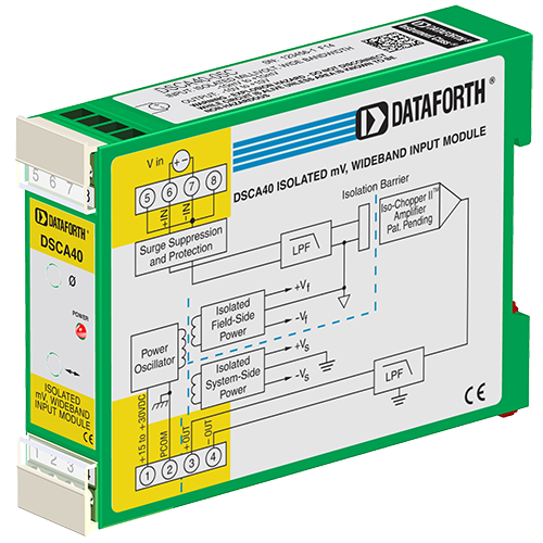
Each DSCA40/41 voltage input module provides a single channel of analog input which is filtered, isolated, amplified, and converted to a high-level voltage output. Signal filtering is accomplished with a five-pole filter. An anti-aliasing pole is located on the field side of the isolation barrier, and the other four poles are on the system side. After the initial field-side filtering, the input signal is chopped by a proprietary chopper circuit. Isolation is provided by transformer coupling, again using a proprietary technique to suppress transmission of common mode spikes or surges.

Module output is either voltage or current. For current output models a dedicated loop supply is provided at terminal 3 (+OUT) with loop return located at terminal 4 (-OUT). The system-side load may be either floating or grounded.

Special input circuits provide protection against accidental connection of powerline voltages up to 240VAC and against transient events as defined by ANSI/ IEEE C37.90.1. Protection circuits are also present on the signal output and power input terminals to guard against transient events and power reversal. Signal and power lines are secured to the module using screw terminals which are in pluggable terminal blocks for ease of system assembly and reconfiguration.

The modules have excellent stability over time and do not require recalibration, however, zero and span settings are adjustable up to ±5% to accommodate situations where fine-tuning is desired. The adjustments are made using potentiometers located under the front panel label and are non-interactive for ease of use.

Specifications

  • Input Range -50 to +50 mV
  • Output Range 4 to 20 mA
  • Bandwidth 3 kHz
  • Mechanical Format DIN rail
  • Isolation Voltage 1500 Vrms
  • Isolation Type Transformer 3-way
  • Accuracy ±0.03% Span
  • Supply Voltage 15 to 30 Vdc (+24V Nom)
  • Input Voltage Withstand 240 Vrms
  • Gain/Offset Adjust ±5%
  • NMR (60 Hz) Rejection 100dB/decade above 3 kHz
  • External I-to-V Resistor N/A
  • Output Control Always enabled
  • Output Resistance <1 Ohm
  • Dimensions 2.95 x 0.89 x 4.13 inches
  • Interface 8 Pos terminal block
  • Customization yes
  • Weight 99 grams (3.49 ounces)

Features

  • Accepts Millivolt and Voltage Level Signals
  • Industry Standard Output of either 0-10V, ±10V, 0-20mA, or 4-20mA
  • 1500Vrms Transformer Isolation
  • ANSI/IEEE C37.90.1 Transient Protection
  • Input Protected to 240VAC Continuous
  • True 3-Way Isolation
  • Wide Range of Supply Voltage
  • 100dB CMR
  • 3 kHz Signal Bandwidth
  • ±0.03% Accuracy
  • ±0.01% Linearity
  • Easily Mounts on Standard DIN Rail
  • C-UL-US Listed
  • CE and ATEX Compliant

Block Diagram

DSCA40/41 block diagram

Accessories

DSCAX-01
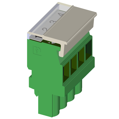
Connector Plug Labeled 1,2,3,4 View
DSCAX-02
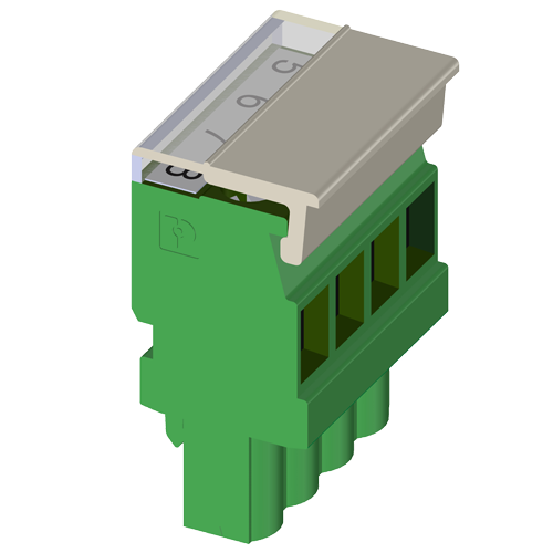
Connector Plug Labeled 5,6,7,8 View
DSCX-BLANK
Blank Empty DIN Rail Case for Holding Positiion. DSCA or DSCT View
PWR-PS5R120W
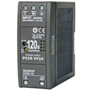
Power Supply, DIN Rail Mount, 85-264 VAC 47-63 Hz In, 24 VDC 5.0 A Out View
PWR-PS5R15W
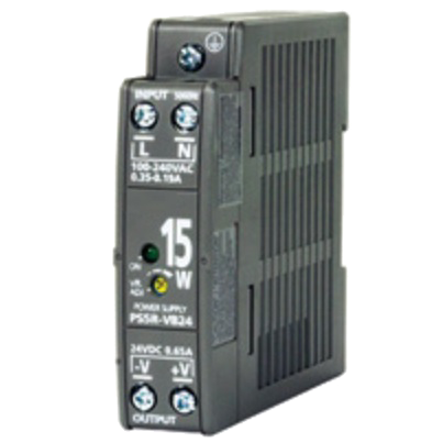
Power Supply, DIN Rail Mount, 85-264 VAC 47-63 Hz In, 24 VDC 0.65 A Out View
PWR-PS5R30W
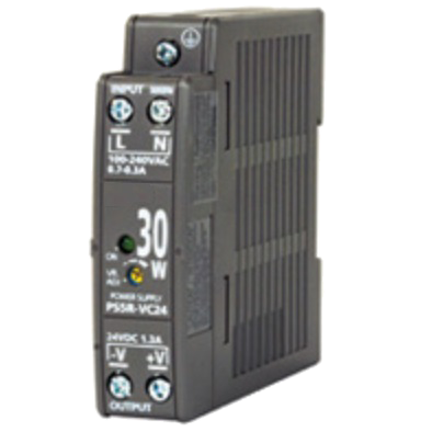
Power Supply, DIN Rail Mount, 85-264 VAC 47-63 Hz In, 24 VDC 1.3 A Out View
PWR-PS5R60W
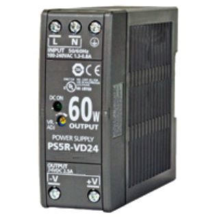
Power Supply, DIN Rail Mount, 85-264 VAC 47-63 Hz In, 24 VDC 2.5 A Out View
PWR-PS5R7W
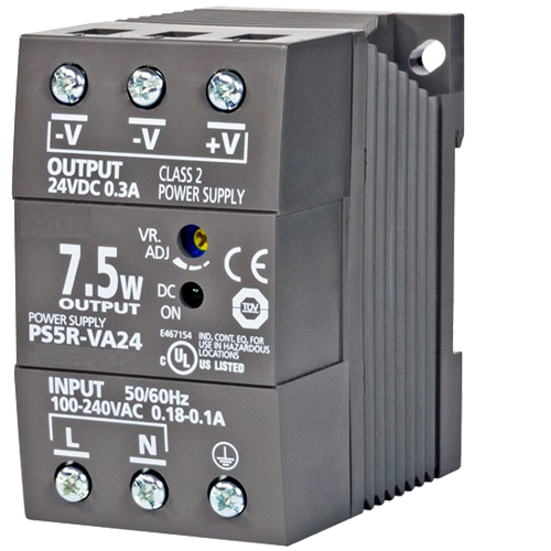
Power Supply, DIN Rail Mount, 85-264 VAC 47-63 Hz In, 24 VDC 0.3 A Out View
SCMXRAIL1-1.0
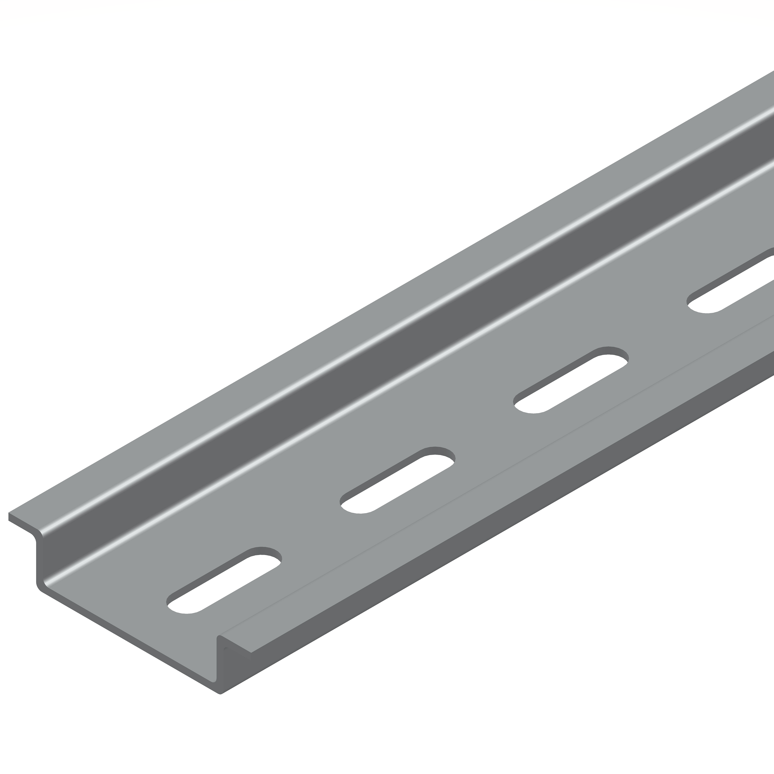
DIN EN 50022-35 x 7.5 (slotted steel), 1 meter length View
SCMXRAIL1-2.0
DIN EN 50022-35 x 7.5 (slotted steel), 2 meter length View
SCMXRAIL2-01
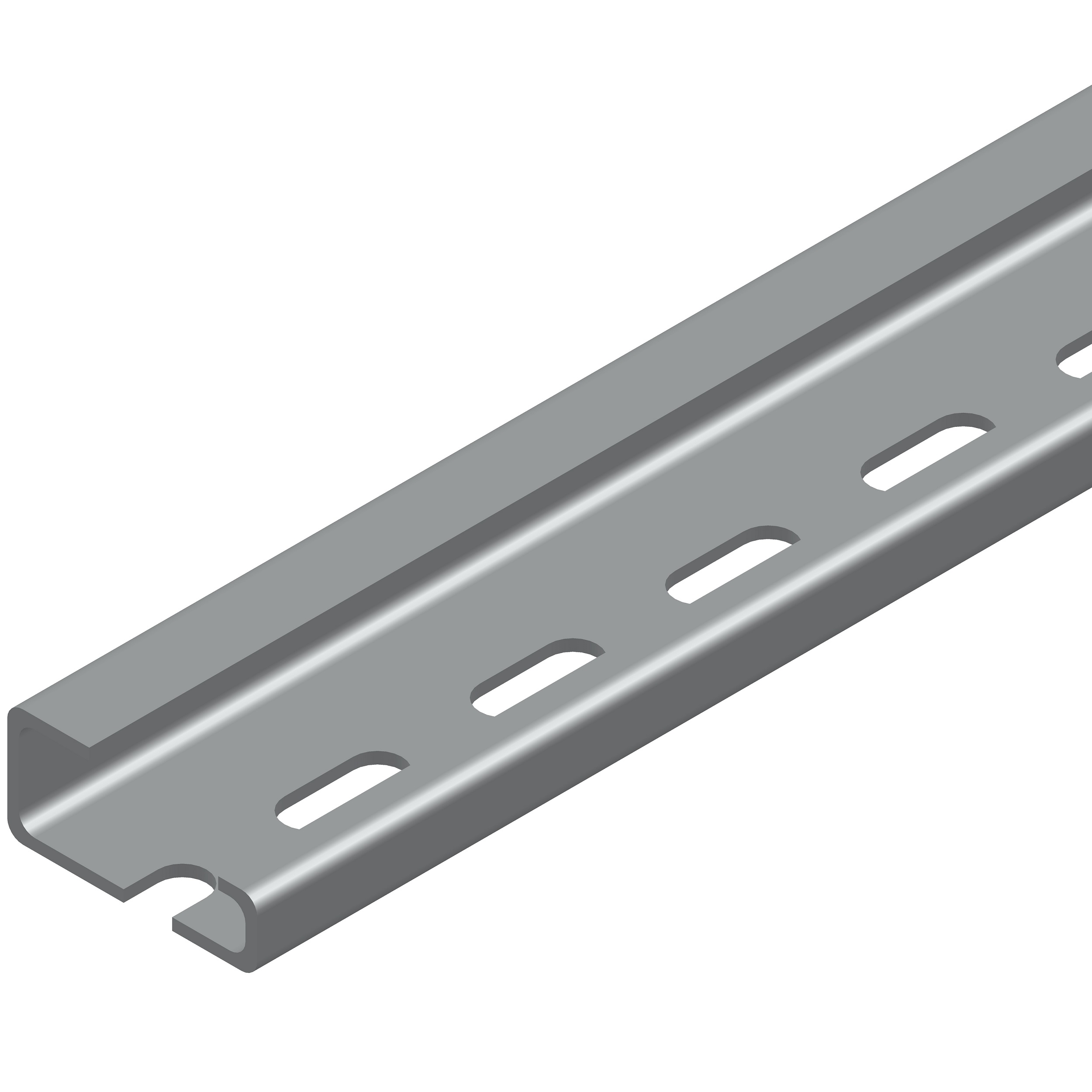
DIN EN 50035-G32 (slotted steel), 1 meter length View
SCMXRAIL2-02
DIN EN 50035-G32 (slotted steel), 2 meter length View
SCMXRAIL3-01
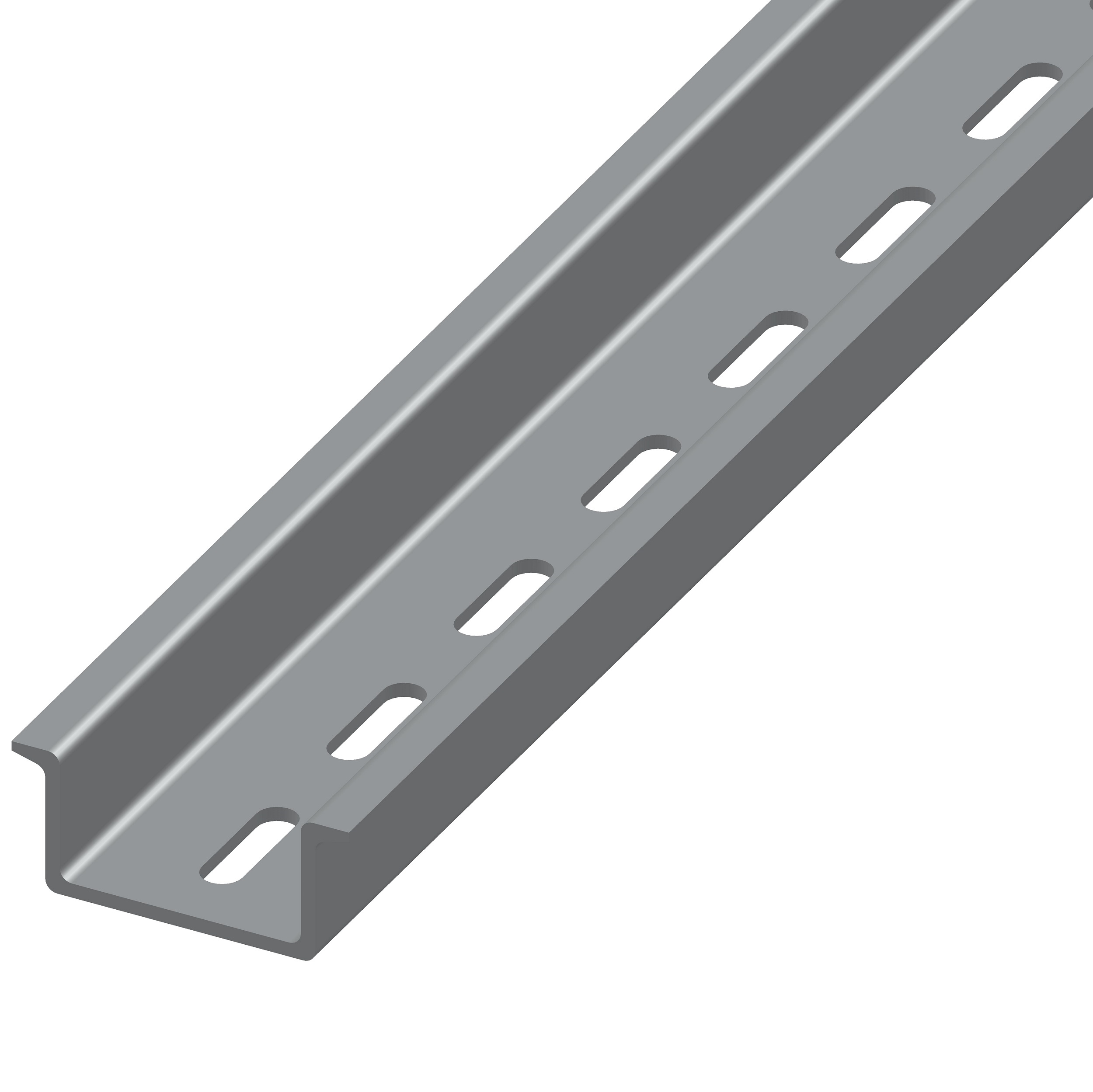
DIN EN 50022-35 x 15 (slotted steel), 1 meter length View
SCMXRAIL3-02
DIN EN 50022-35 x 15 (slotted steel), 2 meter length View

Competitive Cross-Reference

  • No cross reference is available.
View Dataforth cross-reference data.
The information available through this competitive cross reference guide are based upon product catalog information obtained from a variety of sources. The competitive cross reference information is being provided to you free of charge for your use. While Dataforth Corp has used reasonable efforts to ensure data accuracy, Dataforth Corp does not guarantee that it is error-free, nor does Dataforth Corp make any other representation, warranty or guarantee that the information is accurate, correct, reliable or up-to-date. Dataforth Corp expressly disclaims all implied warranties regarding this information, including but not limited to any implied warranties of merchantability or fitness for a particular purpose.

This information is provided only as a convenience on an "as is" basis and Dataforth Corp. or its representatives or distributors are not responsible for any incorrect, inaccurate, or incomplete information. You are solely responsible for (1) selecting the appropriate Dataforth products for your application, (2) designing, validating and testing your application, and (3) ensuring your application meets applicable standards, and any other safety, security, or other requirements.

FAQ

Can Dataforth analog modules be used in high vibration environments? If so, what type of testing or certification was completed?
SCM5B, SCM7B, 8B SensorLex, and DSCA modules are well suited for use in high vibration environments. These modules and their associated accessories have undergone testing for random vibration, shock, and swept sine wave vibration. Details of each of these testing methods are provided below: Random Vibration (Operating): ○ MIL-STD 202G, Method 214A, Condition 1 - Frequency Range: 50-2000Hz, flat spectrum - Vibration Intensity: 7.56 Grms - Duration: 10min/axis (X, Y, Z) Shock (Operating): ○ MIL-STD-810F, Method 516.5 - Pulse Shape: Sawtooth - Test Level: 30G - Duration 11ms - Orientation: +/-X, +/-Y, +/-Z Swept Sine Vibration (Operating) ○ MIL-STD-810G, Method 514.6, modified - Frequency Range: 10-2000Hz - Vibration Intensity: 5Gp-p - Sweep Rate: 1 octave/min - Orientation: X, Y, Z Declaration of conformity for the above-listed tests can be provided upon customer request. Please contact customer service if a copy of the declaration is needed.
Due to resource constraints on my computer, I'm unable to open the three dimensional CAD models provided on your website. Does Dataforth provide two demensional CAD models for download as well?
Two dimensional CAD models can be generated upon customer request. Please contact Customer Service for assistance.
What does it mean when an input module has for example a 3kHz bandwidth?
A 3kHz bandwidth on an input module means it can accept voltages from DC to 3000Hz. Any frequency higher than that and the signal will start to be attenuated by the filter at the input.
What does "Response time, 90% span" mean on the datasheet for my module?
Normally, a response time figure refers to how quickly a module's output can "respond" to a change in the input signal. "Response time, 90% span" refers to how fast a module can adjust its output when a step signal is applied at the input, where the magnitude of this step input is 90% of the input span of the module.
Do DSCA modules come with screw terminal blocks installed?
Yes, DSCA modules do come with the screw terminal blocks installed. The screw terminal accessories listed in our catalog are intended as replacements in case a terminal block is damaged or lost.
What size wires do the DSCA modules accept?
DSCA module screw terminals are rated to wire gage AWG: 28 – 12.
Will I damage the input of my DSCA40-02 if I apply a 12V signal?
All DSCA40 and DSCA30 modules are input protected up to a continuous 240Vrms signal. 12V is well below that rating and will not damage the module.
How far can I overrange my DSCA30/31/40/41 module? What will the effects be on the module/output?
The overrange capability is approximately 10% of the input range unless otherwise specified in the datasheet. Beyond that level the output will become nonlinear and will clamp either at a reference or power supply rail. Accuracy and linearity are not guaranteed over the minimum and maximum output. The module will not be damaged in any way unless the input exceeds the input protection specification, which is 240Vrms continuous.
Where can I find the MTBF of my module?
Information on MTBF for SCM5B, SCM7B, 8B and DSCA is available on our website. Please see application note AN802 for more details. Application notes can be found under the "Literature" tab on the top navigation bar.
Is the calibration of Dataforth modules traceable to NIST standards?
Yes, calibration of Dataforth modules is traceable to NIST standards.
Can the DSCA30/31-xx be modified to have a faster response time?
The DSCA30/31-xx series cannot be modified to have a faster response time. However, the DSCA40/41-xx series is the direct equivalent of the DSCA30/31-xx series, but with a wider bandwidth and faster response time.
What is the output resolution of the DSCA series?
The DSCA series is completely analog, so the output resolution cannot be expressed in terms of bits as it is not a digital signal. The only thing that would cause any uncertainty/lack of clarity in your output signal would be the output ripple and noise, which is rated at a typical value of 0.025% span RMS as listed in the datasheet.
Does Dataforth have any DSCA modules that can operate on a 12Vdc power supply?
Dataforth does not have any custom modules that run on 12VDC power. Most DSCA modules require a minimum power supply voltage of 15VDC while some require a minimum of 19VDC. Both are suitable for use with nominal 24VDC power supplies over the full operating temperature range of -40C to +85C. Dataforth offers a line of accessory power supplies, PWR-PS5RxW, which have been qualified for use with the DSCA product line. https://www.dataforth.com/catalog/pdf/PWR-PS5RxW.pdf
How does the load resistance of a module affect the noise at the output?
Noise at the output of a module is independent of load resistance.
How do I convert an RMS voltage to its corresponding peak voltage?
To convert an RMS voltage to its corresponding peak voltage, you simply take the RMS voltage value and multiply it by the square root of 2, or roughly 1.414. For example, 1500Vrms corresponds to a peak voltage of 1500 * 1.414 = 2121 Vp
If the input range of my signal conditioner is -1V to +1V and the output range is 0 to 10V, does this mean that it ignores polarity?
A signal conditioner with these I/O ranges does not mean that the module ignores the polarity of your voltage input. The output of voltage input modules are scaled linearly, meaning an input of -1V would correspond to an output of 0V, an input of 0V would correspond to an output of 5V, an input of +1V would correspond to an output of 10V, and so on.
Can Dataforth provide calibration reports for modules I purchased?
Yes we can provide calibration reports for the modules that you purchased. You can either a) visit https://www.dataforth.com/TestDataReport.aspx to search for Test Report Datasheets by Serial Number or b) you can send us a list of model numbers and their serial numbers to support@dataforth.com
Could you explain, what is the main difference between the DSCA41 and the DSCA49?
The main difference is the DSCA41 is an input module and the DSCA49 is an output module, which means:

A. The DSCA41 module has its input on the isolated field side of the module, connected to it through screw terminals 6 and 7. The DSCA41 module has its output on the system and power supply side of the module, connected to it through screw terminals 3 and 4.

B. The DSCA49 module has its output on the isolated field side of the module, connected to it through screw terminals 6 and 7. The DSCA49 module has its input on the system and power supply side of the module, connected to it through terminals 3 and 4.

Keywords/Phrases: DSCA, DSCA module, DSCA input module, DSCA output module, DSCA41, DSCA49

Was this content helpful?
Thank you for your feedback!
Menu
Top