Filtering Noise
Tech Note
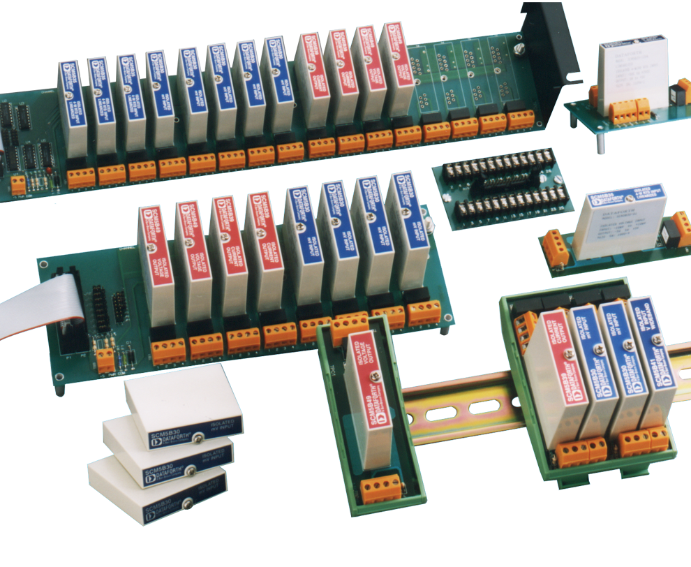
Signal conditioning modules, SCMs, used for measuring process control variables such as temperature, pressure, strain, position, speed, level, etc. are always subject to externally induced noise signals. Noise sources in the form of electro-magnetically induced voltages (or currents) in industrial measurement and control systems are inevitable. Most noise voltages are induced directly as a result of changing magnetic fields such as power line 60 Hz (and associated harmonics and surges), electric motor variable speed drives, weather caused electrical storms, etc.
Special shielded wires, protective conduits, shielded cable trays together with isolation methods and proper grounding techniques often help minimize the effects of these detrimental induced noise levels. It is, however, an unfortunate fact that in many cases such prevention techniques do not adequately reduce all these induced noise signals. Often preventative techniques that are successful in one area of a facility fail when applied in another area. For example, techniques used in the third floor dye room, may fail in the basement welding shop.
Noise filters embedded within signal conditioning modules provide one of the most effective methods used to attenuate induced noise signals. The transmission (direct or 4-20mA) of industrial process measurements such as temperature, pressure, strain, position, speed, level, etc are typically in the low frequency range and require low pass (LP) filters to eliminate high frequency induced noise. Low pass filters transmit all signals below a cutoff frequency and prevent signal transmission above this cutoff point.
Low pass filters are typically characterized by their cutoff frequency, often referred to as bandwidth, and the number of their circuit poles. Cutoff frequencies are defined as the frequency where signal transmissions have fallen to 70.7%, or where output power has dropped to 50% or where signal transmission has fallen by 3 decibels [dB = 20* log (Vout/Vin)].
The number of circuit poles characterizes the shape of a low pass filter’s attenuation curve beyond their cutoff. One can estimate that filter attenuation beyond cutoff is 20 dB per decade change in frequency for each circuit pole. For example, single pole LP filters have an attenuation curve slope of only 20 dB per decade change in frequency, whereas a 7-pole LP Filter has a 140 dB per decade slope.
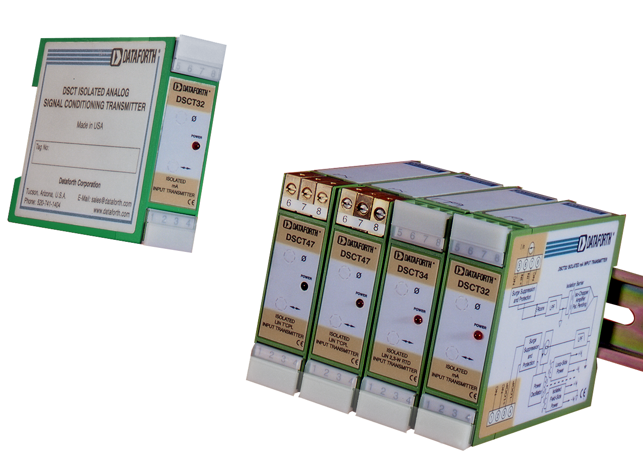
Dataforth SCMs employ multiple pole LP filters; 5-poles to 7-poles depending upon the specific application, Moreover, all Dataforth’s isolated SCMs have filtering on both the field side and output side with antialiasing characteristics on the field side.
For example, on the first page of the following data sheet you see a typical block diagram with the depiction of low pass filters on both the field-side and system-side of the circuit. On the second page of this data sheet you can see how we state bandwidth, attenuation per decade (NMR = Normal Mode Rejection) and step response time (time it takes to output to 90% of a fast change on the input).
Dataforth Strain Gage Input Conditioner DSCA38 (166kb pdf file)
Remember, our Application Engineers can assist you with signal conditioner selection over the phone or via fax and email. Call us at our manufacturing facility in Tucson at 520-741-1404 (fax 520-741-0762) or Email us at support@dataforth.com.
Was this content helpful?
Thank you for your feedback!

