


Introduction To Thermocouples
Tech Note
Preamble
Thomas Johann Seebeck accidentally discovered the Thermocouple in 1821. He experimentally determined that a voltage exists between the two ends of a conductor when the conductors ends are at different temperatures. His work showed that this voltage is proportional to the temperature difference. His discovery soon became the basis of the thermocouple, which today is one of the most popular and cost effective temperature sensors.Thermocouple Theory, How they really work
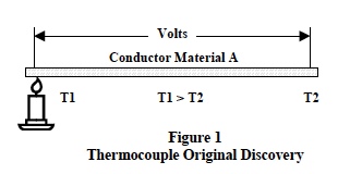
Figure 1 illustrates Seebecks discovery. The open-circuit voltage between conductor ends was proportional to the temperature difference (T1-T2) as shown in Equation 1.

Where Sa is the Seebeck coefficient, defined as the thermoelectric power of a material.
Modern theories of electron behavior within a materials molecular structure provide an analytical explanation of the Seebeck phenomena. The detail mathematics is very complex and involves electron quantum theory; however, the fundamental concept is straightforward.
The molecular structures of electrical conductors is such that electrons within the material are loosely coupled to their host lattice sites (nuclei) and, are available to move throughout the material when energized.
When one end of a conductive material is heated to a temperature larger than the opposite end, the electrons at the hot end are more thermally energized than the electrons at the cooler end. These more energetic electrons begin to diffuse toward the cooler end. Of course, charge neutrality is maintained; however, this redistribution of electrons creates a negative charge at the cool end and an equal positive charge (absence of electrons) at the hot end. Consequently, heating one end of a conductor creates an electrostatic voltage due to the redistribution of thermally energized electrons throughout the entire material. This is the Seebeck effect and the basic principal of thermocouples.
Equation 1 provides the analytic expression for this phenomenon where the term Sa embodies all the complex quantum electron behavior within a solid and is dependent entirely on the materials molecular structure. As one might expect, the thermoelectric power (Sa) is non-linear depending on a materials internal molecular structure and its temperature.
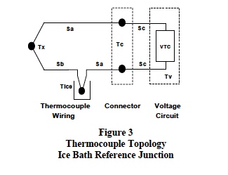
Seebecks experimental work showed that if a voltmeter circuit wiring and the conductor under test were both the same material, then the net loop voltage is zero because [Sa*(T1-T2)+Sa*(T2-T1)=0]. A net loop voltage appeared only when measurements were made across the open ends of two dissimilar conductors connected together with the connected end at a different temperature than the open ends. The topology of this situation is shown in Figure 2, which characterizes a typical thermocouple connection for measuring temperature difference.
Analysis of the topology shown in Figure 2 illustrates Seebecks fundamentals of thermocouple behavior
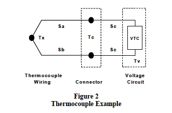 Definitions for the situation shown in Figure 2 are;
 - Tx is the unknown temperature.
- Tc is the temperature at the voltmeter connector (assumed the same for both wires).
- Tv is the internal temperature of all the voltmeter circuit elements.
- Sa is the Seebeck coefficient of thermocouple wire material a.
- Sb is the Seebeck coefficient of thermocouple wire material b.
- Sc is the Seebeck coefficient of the wiring used in the voltage measuring circuit.
- The Voltage Circuit measures thermocouple open circuit voltage (VTC) with a high impedance circuit to minimize loop current.
Definitions: (Sa-Sb) = Sab and (Sb-Sa) = -Sab
These terms are defined by industry standards as the Sab Seebeck coefficient signifying a type ab thermocouple made of material a and b.
Important Observations
The analysis used to develop Equation 3 provides the following important characteristics of thermocouple behavior;
- Thermocouple action between two different materials (Seebeck Effect) is a material phenomenon that depends solely on the materials internal molecular structure and does not depend on the type of junction between materials. The junction only needs to be a good electrical contact.
- Thermocouples measure temperature difference between the junction end and the open end; they do not measure the individual temperature at a junction.
- Both thermocouple wires at the connection to the voltage measuring circuit establish unwanted thermocouple junctions between the connector at temperature (Tc) and the voltmeter circuit wires at temperature (Tv). If these two parasitic junction connections are both at temperature Tc, and if all elements in the voltmeter circuit are at temperature (Tv), then the effect of these parasitic junctions cancel. This condition becomes a requirement for using thermocouples.
- Thermocouple voltages must be measured with high impedance circuits to keep loop current near zero. Current flow in thermocouples can create errors by disturbing the thermal distributions of electrons.
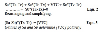
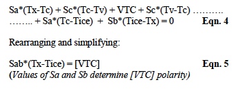
The thermocouple circuit shown in Figure 3 represents the basis upon which thermocouple standard tables have been established. A new junction is added and held in an ice bath at Tice (0°C/32°F). The standards community and thermocouple manufacturers use this topology to develop tables of thermocouple voltage versus temperature.
Analyzing the topology in Figure 3 with Equation 1 and the technique used for establishing Equations 2 and 3 above gives;
This thermocouple temperature measurement technique was developed in about 1828. Since then, thermocouple materials, tables, and analytical models have had well over 172 years to mature into a very cost effective temperature measurement scheme.
Modern signal conditioning modules use semiconductor electronics, which eliminate clumsy ice-baths by electronically simulating reference junction ice-point temperatures. This process is referred to as Cold-Junction-Compensation, CJC. In addition, these modern signal-conditioning modules linearize the non-linear behavior of Seebeck coefficients and provide linear scaled outputs in volts or amperes per degree.
For these CJC and linearization techniques, additional thermocouple application details, and thermocouple interface products the reader is encouraged to examine Datforths website. Also, the reader is encouraged to review Dataforths AN107, Practical Thermocouple Temperature Measurements, for a further practical discussion of thermocouples, Ref 2.
Was this content helpful?
Thank you for your feedback!