


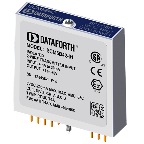
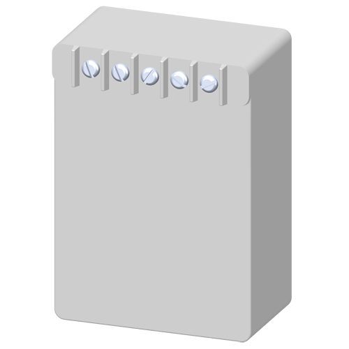
SCM5B42-01
Current Input Module with 2-Wire Transmitter Power Supply
SCM5B42-01
Current Input Module with 2-Wire Transmitter Power Supply
Product Availability:
- Usually stock to 3-5 weeks. Contact Customer Service for current lead times.
SCM5B42-01 added to cart.
Description
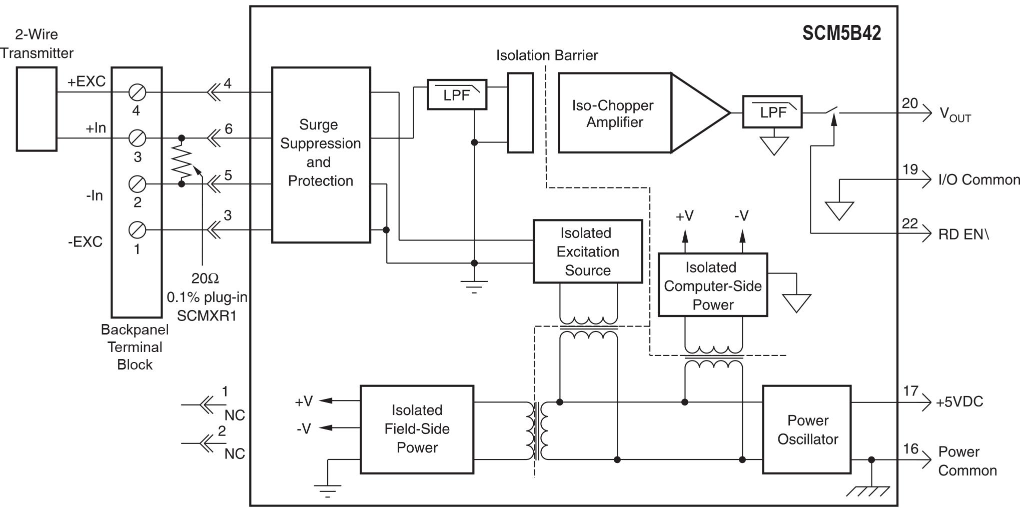
Each SCM5B42 2-wire transmitter interface module provides a single channel which accepts a 4 to 20mA process current input and provides a standard +1 to +5V or +2 to +10V output signal . An isolated +20VDC regulated power supply is provided to power the current transmitter. This allows a 2-wire loop powered transmitter to be directly connected to the SCM5B42 without requiring an external power supply. The regulated supply will provide a nominal +20VDC at a loop current of 4mA to 20mA.The SCM5B42 will provide a 1500V isolation barrier for non-isolated 2-wire field transmitters. It can also be used when additional isolation is required between an isolated 2-wire transmitter and the input stage of the control room computer.
The voltage output is logic switch controlled, which allows these modules to share a common analog bus without the requirement of external multiplexers.
The SCM5B modules are designed with a completely isolated computer side circuit which can be floated to ±50V from Power Common, pin 16. This complete isolation means that no connection is required between I/O Common and Power Common for proper operation of the output switch. If desired, the output switch can be turned on continuously by simply connecting pin 22, the Read-Enable pin, to I/O Common, pin 19.
A precision 20 ohm current conversion resistor is supplied with the module. Sockets are provided on the SCMPB01/02/03/04/05/06/07 backpanels to allow installation of this resistor. Extra resistors are available under part number SCMXR1. All field inputs are fully protected from accidental connection of power-line voltages up to 240VAC. The module has a 3dB bandwidth of 100Hz. Signal filtering is accomplished with a six-pole filter, with two poles on the field side of the isolation barrier, and the other four on the computer side.
Features
- Isolated +20VDC Current Loop Supply
- Provides Isolation for Non-Isolated 2-Wire Transmitters
- High-Level Voltage Output +1V to +5V or +2V to +10V
- 1500Vrms Transformer Isolation
- ANSI/IEEE C37.90.1 Transient Protection
- Input Protected to 240VAC Continuous
- 100dB CMR
- 100Hz Signal Bandwidth
- ±0.03% Accuracy
- ±0.005% Linearity
- CSA Certified, FM Approved, CE and ATEX Compliant
- Mix and Match SCM5B Types on Backpanel
Block Diagram
Documents
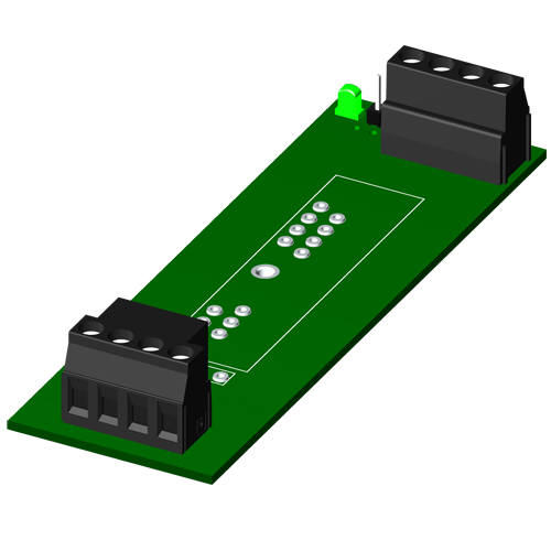
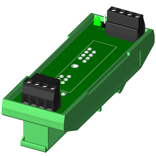
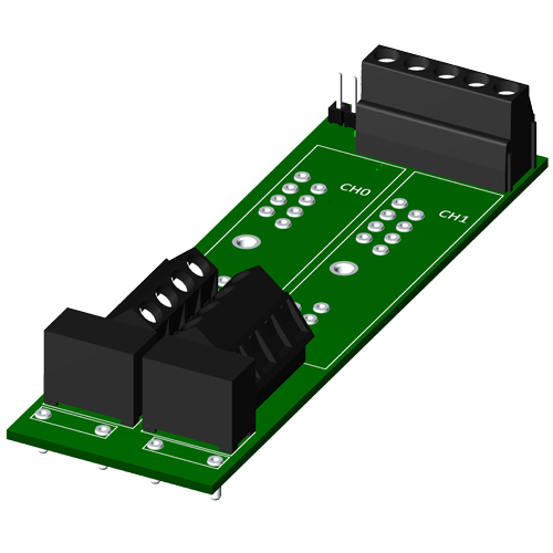
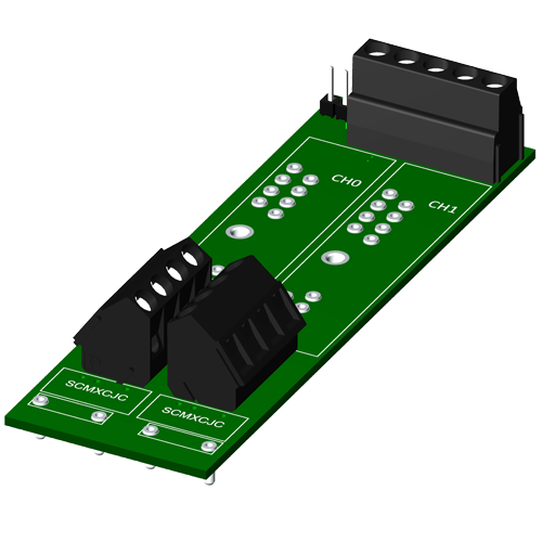
CAD Model
5B Module & Accessory 3-D CAD Models
5B Module & Accessory 3-D CAD Models
Certifications

Specifications
- Input Range 4 to 20 mA
- Output Range +1 to +5 V
- Mechanical Format Modular plug-in-board
- Internal Power Supply Powers 2-Wire Transmitter
- Isolation Voltage 1500 Vrms
- Isolation Type Transformer 3-way
- Accuracy ±0.03%
- Supply Voltage +5VDC ±5%
- Input Voltage Withstand 240 Vrms
- Gain/Offset Adjust N/A
- Module Bandwidth 100 Hz
- NMR (60 Hz) Rejection 120dB per Decade above 100Hz
- External I-to-V Resistor 20 Ohms
- Output Control Enable/Disable
- Output Resistance 50 Ohms
- Dimensions 2.28 x 2.26 x 0.60 inches
- Interface 14 pin
- Customization yes
- Load Resistance
- Weight 62 grams (2.19 ounces)
Accessories
PWR-4505
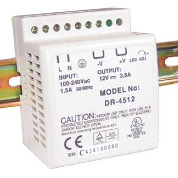
Power supply, 5A, 5VDC, 85 to 264VAC Universal, DIN mount, Switching power supply
View
SCM5B-PROTO
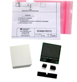
SCM5B breadboard kit
View
SCM5BPT
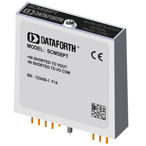
Pass Thru Module, Non-isolated, unity gain
View
SCM5BPT-1367
Pass Thru Module with Switch, Non-isolated, unity gain
View
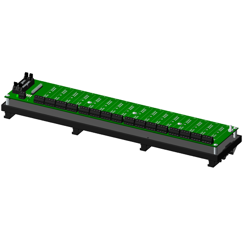
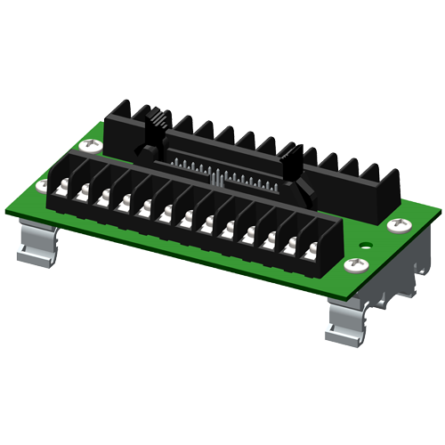
SCMPB01
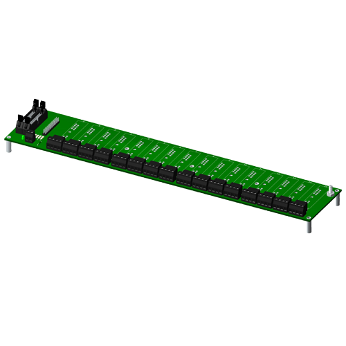
Non-multiplexed, 16 channel backpanel
View
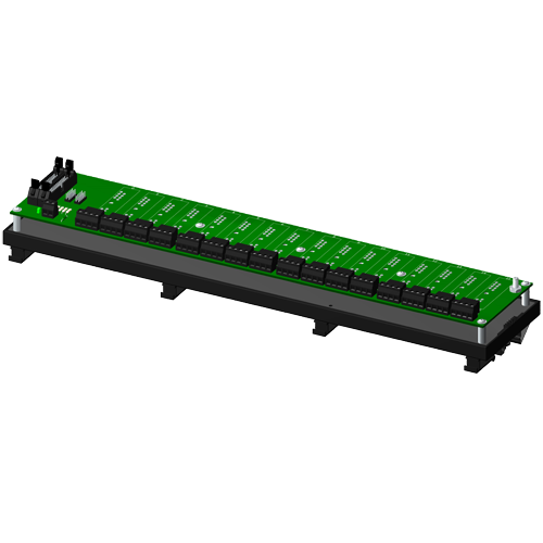
SCMPB01-1
Non-multiplexed, 16 channel backpanel, no CJC
View
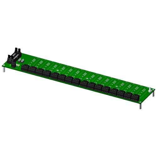
SCMPB01-2
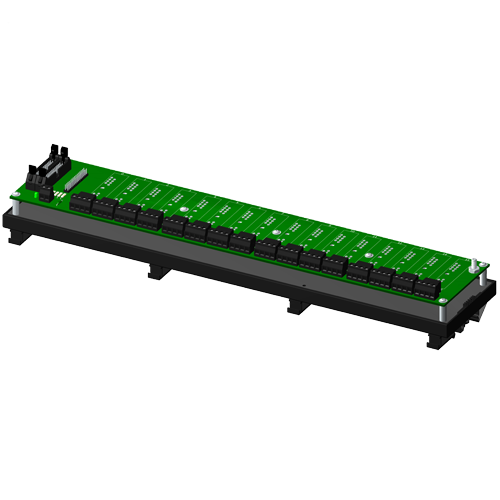
Non-multiplexed, 16 channel backpanel with DIN rail mounting option
View
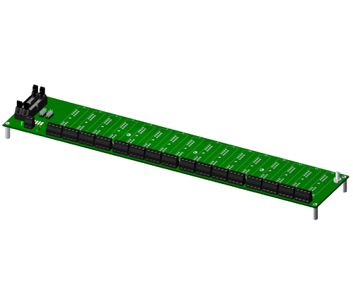
SCMPB01-3
Non-multiplexed, 16 channel backpanel, no CJC, with DIN rail mounting option
View
SCMPB02
Multiplexed, 16 channel backpanel
View
SCMPB02-1
Multiplexed, 16 channel backpanel, no CJC
View
SCMPB02-2
Multiplexed, 16 channel backpanel with DIN rail mounting option
View
SCMPB02-3

Multiplexed, 16 channel backpanel, no CJC, with DIN rail mounting option
View
SCMPB03
Single channel backpanel
View
SCMPB03-2
Single channel backpanel, DIN rail mount
View
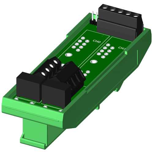
SCMPB04
Dual channel backpanel
View
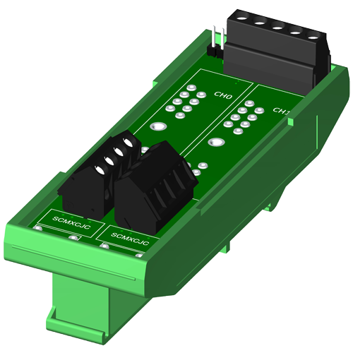
SCMPB04-1
Dual channel backpanel, no CJC
View
SCMPB04-2
Dual channel backpanel, DIN rail mount
View
SCMPB04-3
Dual channel backpanel, DIN rail mount, no CJC
View
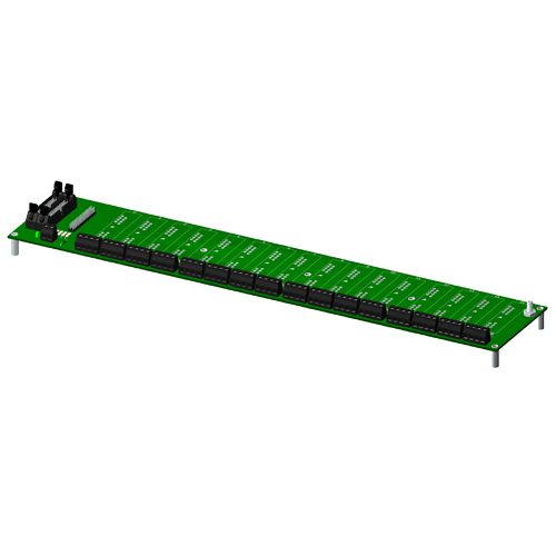
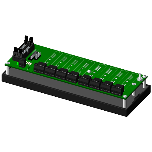
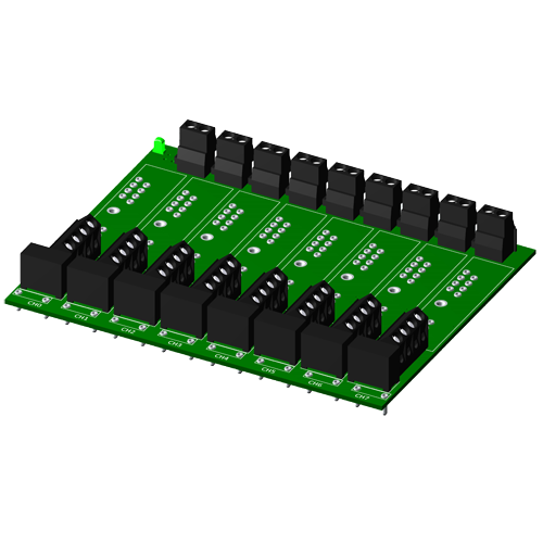
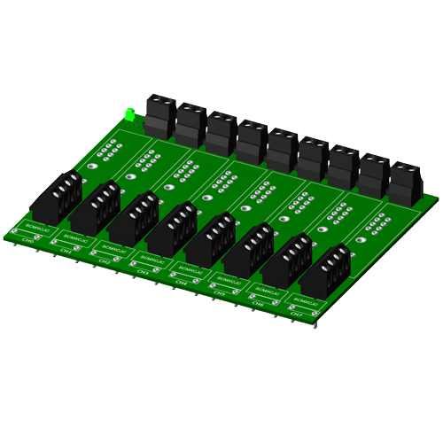
SCMPB05
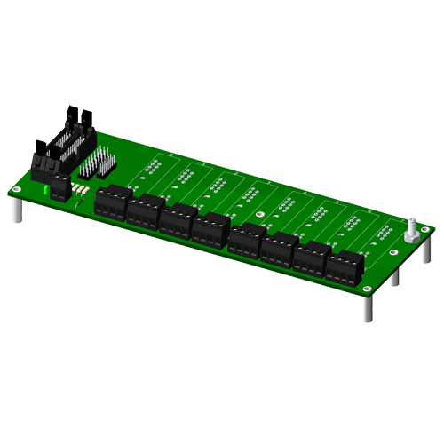
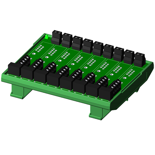
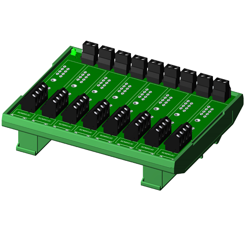
Non-multiplexed, 8 channel backpanel
View
SCMPB05-1
Non-multiplexed, 8 channel backpanel, no CJC
View
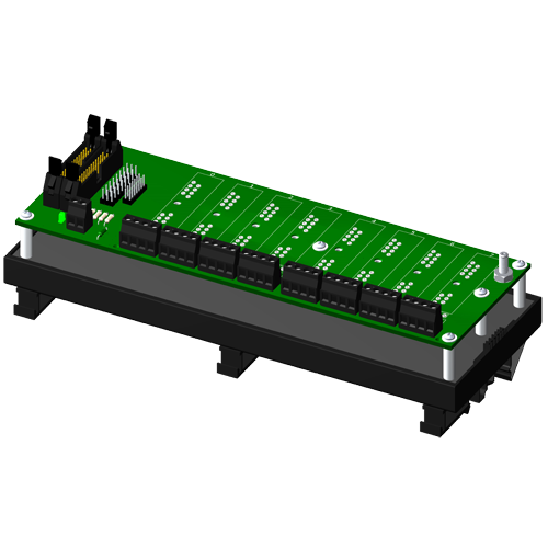
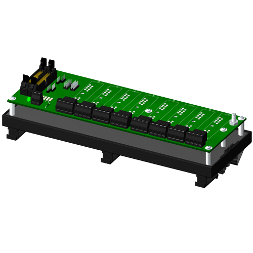
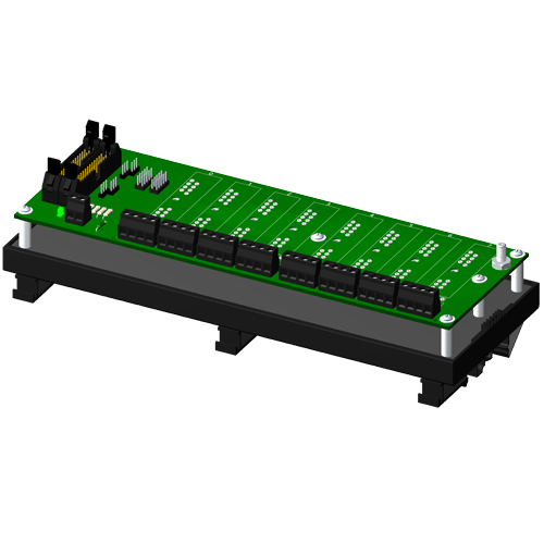
SCMPB05-2
Non-multiplexed, 8 channel backpanel with DIN rail mounting option
View
SCMPB05-3
Non-multiplexed, 8 channel backpanel, no CJC, with DIN rail mounting option
View
SCMPB06
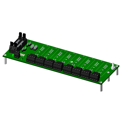
Multiplexed, 8 channel backpanel
View
SCMPB06-1
Multiplexed, 8 channel backpanel, no CJC
View
SCMPB06-2
Multiplexed, 8 channel backpanel with DIN rail mounting option
View
SCMPB06-3
Multiplexed, 8 channel backpanel, no CJC, with DIN rail mounting option
View
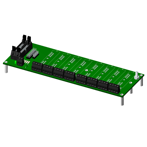
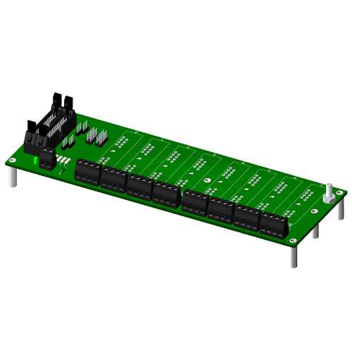
SCMPB07
Non-multiplexed, 8 channel backpanel
View
SCMPB07-1
Non-multiplexed, 8 channel backpanel, no CJC
View
SCMPB07-2
Non-multiplexed, 8 channel backpanel with DIN rail mounting option
View
SCMPB07-3
Non-multiplexed, 8 channel backpanel, no CJC, with DIN rail mounting option
View
SCMXBE
DIN rail base element without snap foot
View
SCMXBEFE
DIN rail base element with snap foot
View
SCMXCA004-01
System interface cable for both analog backpanels, 1 meter length
View
SCMXCA004-02
System interface cable for both analog backpanels, 2 meter length
View
SCMXCJC
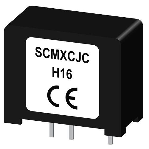
Encapsulated cold junction compensation circuit
View
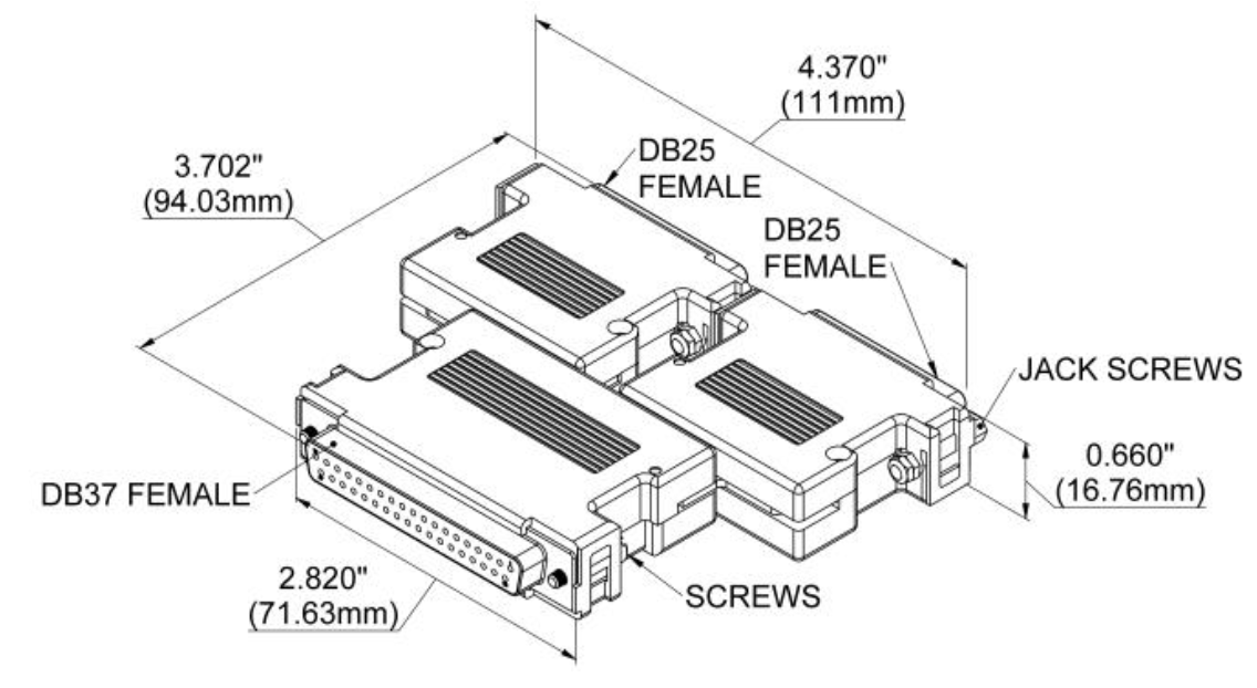
SCMXDB37F25BP00
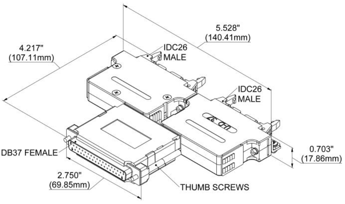
Third Party DAQ Front-Ending Adapter for Dataforth Backpanels
View
SCMXDB37F27BP00
Third Party DAQ Front-Ending Adapter for Dataforth Backpanels
View
SCMXDB37F28BP00
Third Party DAQ Front-Ending Adapter for Dataforth Backpanels
View
SCMXDB37F5BP00
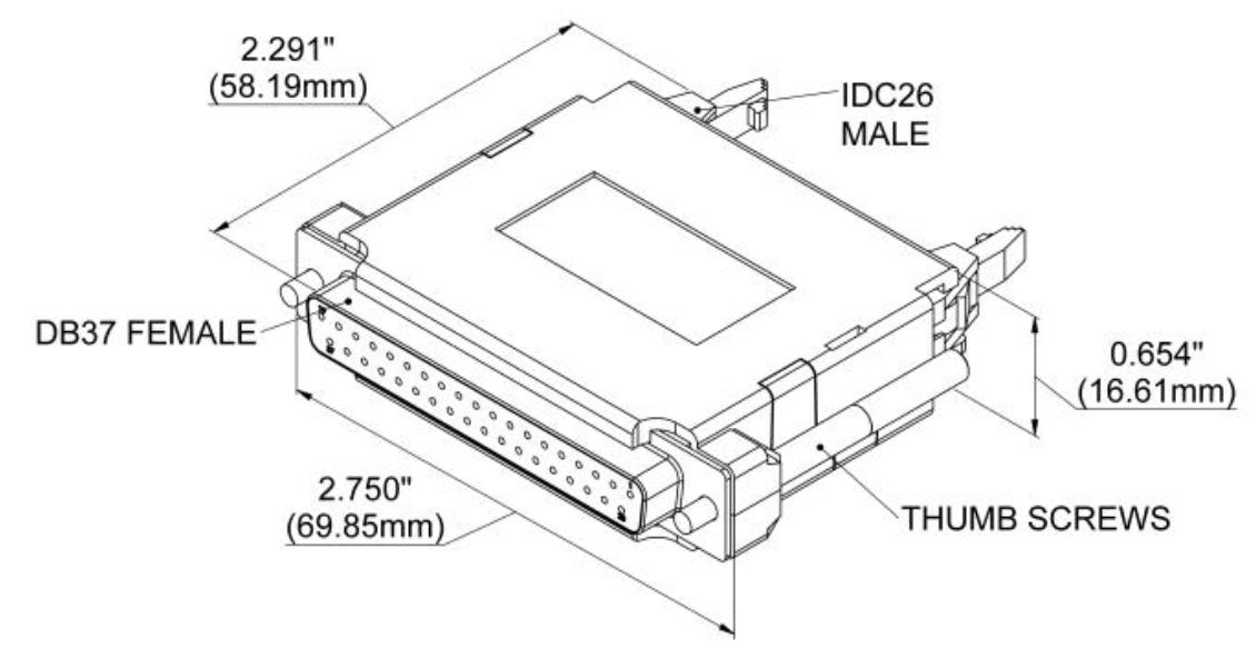
Third Party DAQ Front-Ending Adapter for Dataforth Backpanels
View
SCMXDB37F7BP00
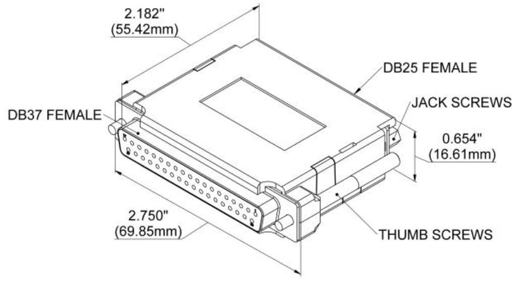
Third Party DAQ Front-Ending Adapter for Dataforth Backpanels
View
SCMXDB37F8BP00
Third Party DAQ Front-Ending Adapter for Dataforth Backpanels
View
SCMXEV
Single channel SCM5B evaluation board
View
SCMXFS-003

Package of 10, 4A fuses
View
SCMXIF
Ribbon cable to screw terminal interface board
View
SCMXIF-DIN
Ribbon cable to screw terminal interface board, DIN mount
View
SCMXJP-003

Package of 10 jumpers
View
SCMXPRE-001

Power supply, 1A, 5VDC, 220VAC European
View
SCMXPRE-003
Power supply, 3A, 5VDC, 220VAC European
View
SCMXPRT-001
Power supply, 1A, 5VDC, 120VAC U.S.
View
SCMXPRT-003
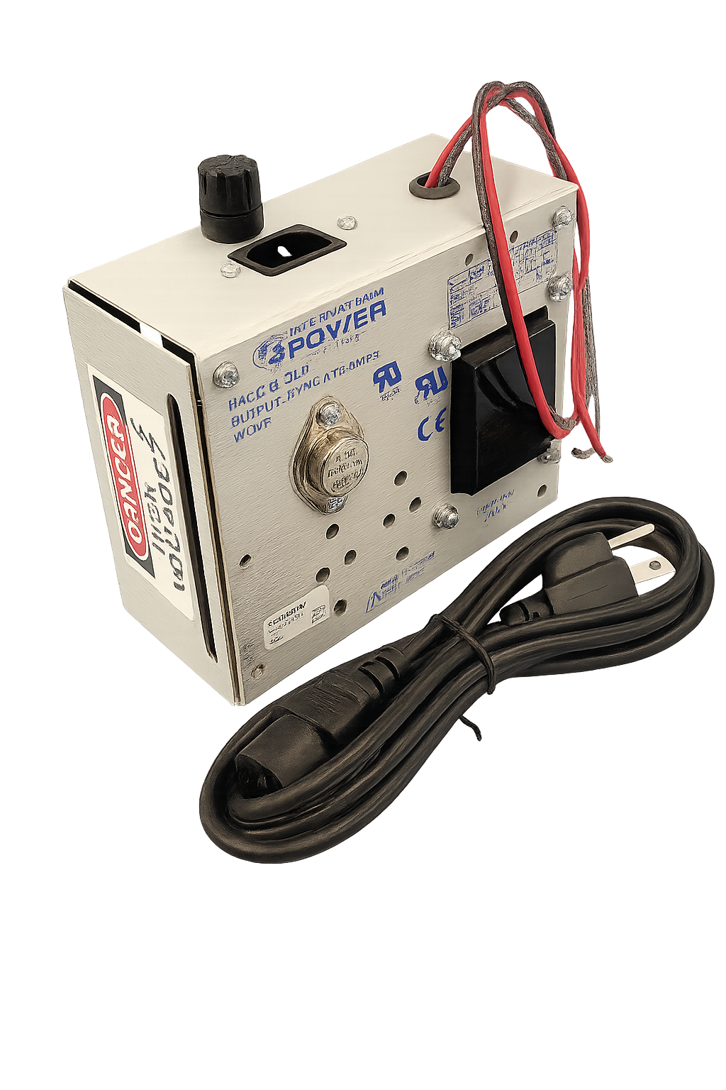
Power supply, 3A, 5VDC, 120VAC U.S.
View
SCMXR1
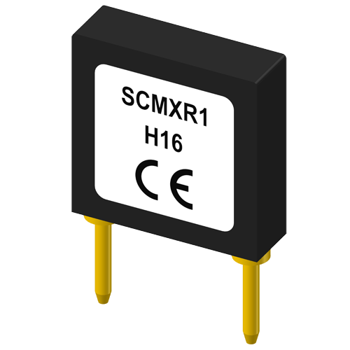
Precision 20 Ohm resistor for SCM5B32 and SCM5B42
View
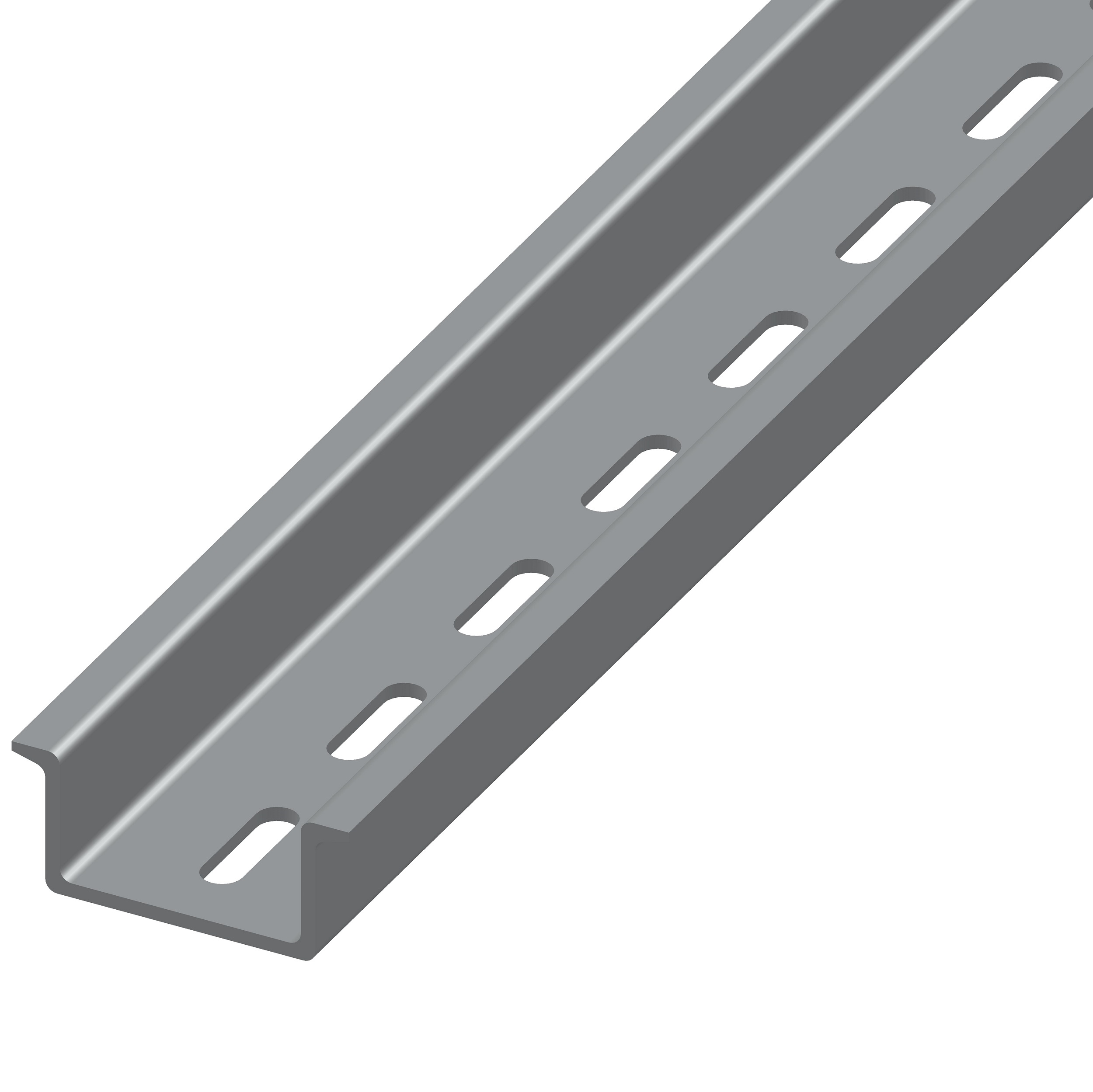
SCMXRAIL1-1.0
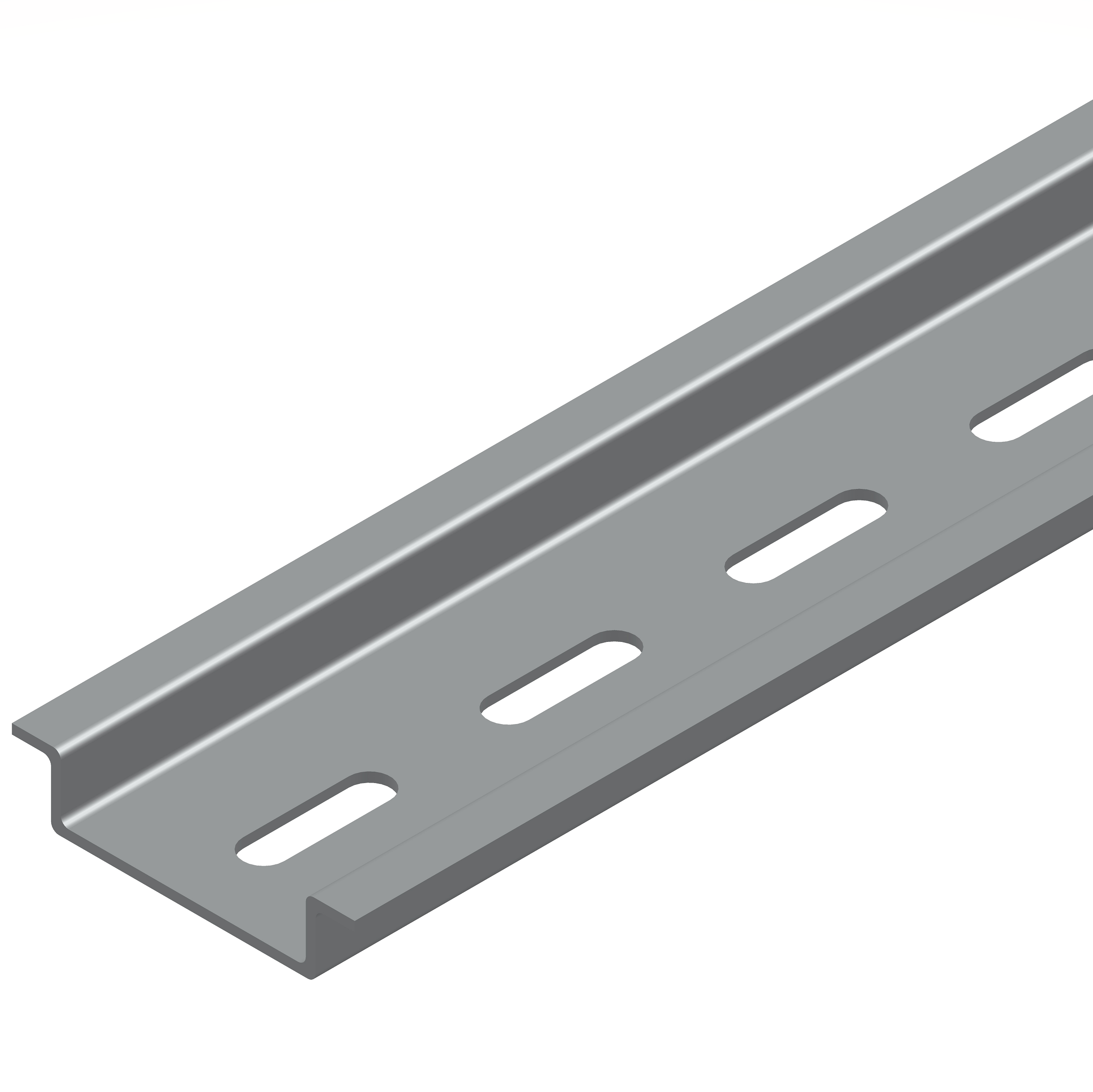
DIN EN 50022-35 x 7.5 (slotted steel), 1 meter length
View
SCMXRAIL1-2.0
DIN EN 50022-35 x 7.5 (slotted steel), 2 meter length
View
SCMXRAIL2-01
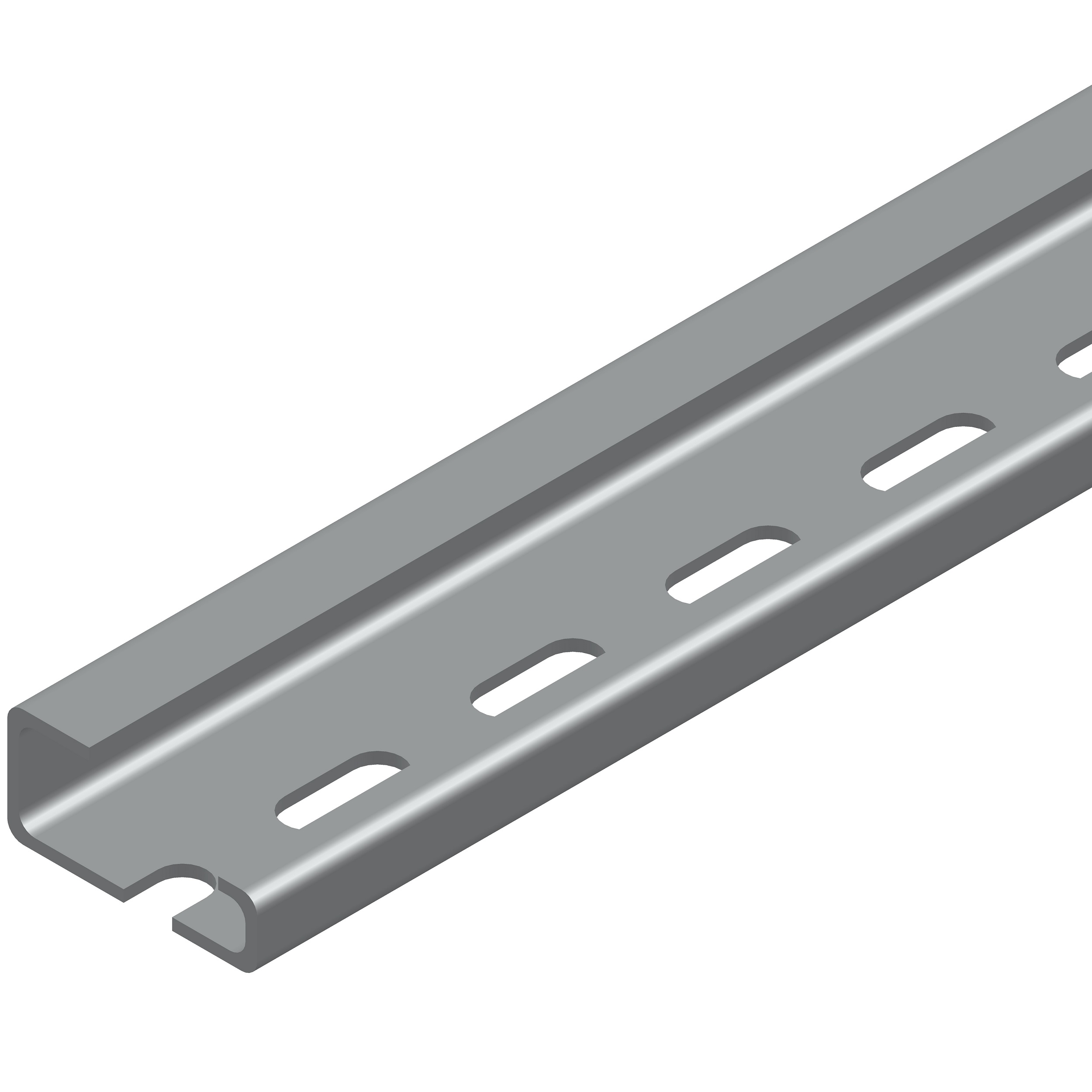
DIN EN 50035-G32 (slotted steel), 1 meter length
View
SCMXRAIL2-02
DIN EN 50035-G32 (slotted steel), 2 meter length
View
SCMXRAIL3-01
DIN EN 50022-35 x 15 (slotted steel), 1 meter length
View
SCMXRAIL3-02
DIN EN 50022-35 x 15 (slotted steel), 2 meter length
View
SCMXRK-002
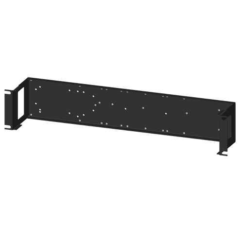
19 inch metal rack for mounting analog backpanels
View
SCMXSE

DIN rail side element
View
SCMXVS
DIN rail connection pins
View
Competitive Cross-Reference
- The SCM5B42-01 equals the Analog Devices NOT AVAILABLE. For specific performance comparison, please review both datasheets.
The information available through this competitive cross reference guide are based upon product catalog information obtained from a variety of sources. The competitive cross reference information is being provided to you free of charge for your use. While Dataforth Corp has used reasonable efforts to ensure data accuracy, Dataforth Corp does not guarantee that it is error-free, nor does Dataforth Corp make any other representation, warranty or guarantee that the information is accurate, correct, reliable or up-to-date. Dataforth Corp expressly disclaims all implied warranties regarding this information, including but not limited to any implied warranties of merchantability or fitness for a particular purpose.
This information is provided only as a convenience on an "as is" basis and Dataforth Corp. or its representatives or distributors are not responsible for any incorrect, inaccurate, or incomplete information. You are solely responsible for (1) selecting the appropriate Dataforth products for your application, (2) designing, validating and testing your application, and (3) ensuring your application meets applicable standards, and any other safety, security, or other requirements.
This information is provided only as a convenience on an "as is" basis and Dataforth Corp. or its representatives or distributors are not responsible for any incorrect, inaccurate, or incomplete information. You are solely responsible for (1) selecting the appropriate Dataforth products for your application, (2) designing, validating and testing your application, and (3) ensuring your application meets applicable standards, and any other safety, security, or other requirements.
FAQ
Was this content helpful?
Thank you for your feedback!