


an108: When Good Grounds Go Bad
Application Note
Preamble
The NEC, National Electrical Code (Ref. 4) requires the installation of grounds for safety and does not allow load currents in ground lines. Unfortunately, unwanted ground currents (Ig) often exist creating undesirable Ig*Zg voltage drops. The impedance (Zg) of grounding systems is normally low; consequently, Ig*Zg drops generally are neglected. This is a normal assumption, since it is assumed that a ground wire represents “ground”, which is the expected zero potential reference. This application note illustrates some situations where unexpected “ground voltages” could cause instrumentation errors.Typical Power Distribution Topologies
There are several general topologies used to supply small to medium sized facilities with electrical energy. Power companies use transformer connections to reduce their high transmission voltages to meet the customer’s low voltage (less than 600 volts) system requirements. These voltages (transformer secondary levels) are illustrated in Figures 1, 2, 3, and 4. These step-down transformer banks are typically located on power poles near the facilities or mounted on concrete pads located outside the customer’s facility. It is important to recognize from Figures 1, 2, 3, 4 that these transformer configurations ground the facility’s supply neutral line to earth, illustrated as Gnd-0.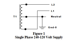
Figure 1 shows a typical transformer secondary connection for the popular single-phase 240/120-voltage distribution system. In this transformer topology, the secondary is a center-tapped connection with 240 volts developed between lines L1-L2 and two 120-volt supplies developed between L1-neutral and L2-neutral. The center tap is neutral, (often referred to as “the return line”) and is earth grounded at this point. Loads that require a 240-volt supply are connected between L1-L2 with no neutral connection, consequently, no neutral current flows in these 240-volt loads. All 120-volt loads are connected either between L1-neutral or between L2-neutral. The neutral current flowing toward the supply Gnd-0 point at any instant in time is the vector sum/difference of all the neutral currents in all the individual 120-volt loads on both L1 and L2. In theory, it is possible to have identical 120-volt loads on L1 and L2 such that the neutral current flowing toward Gnd-0 is zero. However, in practice, this is never realized and there is always some current flowing in the neutral wire toward Gnd-0 at the supply transformers.
This system is often used to provide single-phase 120 V ac voltages while simultaneously providing both single phase 208 and 3-phase 208 voltages. Most modern 220-240 volt equipment is available for use at 208 volts.
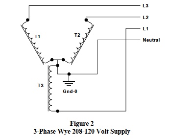
Figure 2 is an illustration of the low voltage secondary side of a three-phase transformer system, which is a wye-connection used to supply 3-phase voltage between L1, L2, and L3. In addition, three each single-phase 208 voltages are available between L1-L2, L2-L3, and L3-L1. In addition, this transformer connection provides three single phase 120-volt supplies; L1-neutral, L2-neutral, and L3-neutral. In this system, single-phase 208-volt loads and balanced three-phase loads, such as motors, welders, heaters, etc create no neutral line current. However, all individual single-phase 120-volt loads connected between lines L1, L2, L3 and neutral contribute to neutral currents flowing toward Gnd-0 at the transformer source.
It is noteworthy to mention here that the mathematics of summing currents in the neutral wire for this topology is a messy complex number exercise and too involved for this article. The results of this exercise show that if all 120-volt loads on L1, L2, and L3 are identical, then the neutral current flowing toward Gnd-0 sums to zero; however, in practice this is never realized and there is always some current flowing in the neutral wire toward Gnd-0 at the supply transformers.
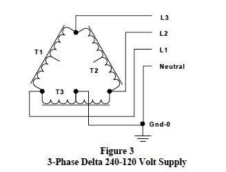
Another popular supply topology is illustrated in Figure 3. In this system, the utility’s supply transformers have their secondary sides connected in a “delta” configuration, which constitutes a 3-phase voltage system. The three lines L1, L2, and L3 constitute a 3-wire 3-phase 240-volt system. Unlike the 4-wire wye 3-phase system, which has a neutral, a 3-wire 3-phase delta voltage system has no neutral. To accommodate the customer’s additional need for single phase 120 volts, one transformer’s 240-volt secondary is center tapped, which provides two 120-volt supplies with the single phase neutral grounded at Gnd-0. The topology shown in Figure 3 provides three lines; L1, L2, and L3, which supply 3-phase 240 volts. Single phase 240 volts (without a neutral) is available between line pairs; (L1-L2), (L2-L3), and (L3-L1). The T3 transformer’s 240-volt secondary is center-tapped, providing the added feature of two single-phase 120 voltages; L2-neutral and L1-neutral. Note: In this system, 208 volts is developed between neutral and L3. This is often referred to as the “wild-leg voltage” and is not used.
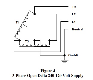
Figure 4 shows an open delta topology used to supply the same system of voltages as the delta system in Figure 3. The open delta topology functions in an identical manner as the “full” delta described above. However, implementation of the open delta requires only two transformers. Utility companies often use this scheme to economically develop 3-phase systems.
In summary, the voltage distribution topologies described above have the following features;
- Manufactured three-phase equipment has balanced phases (equal impedance on each phase); therefore, these loads do not (should not) develop any neutral current flowing in the neutral line back to supply ground, Gnd-0.
- In the 4-wire 3-phase wye system shown in Figure 2, all the single-phase 120-volt loads on L1, L2, and L3 form a composite 3-phase load. In practice, this composite is never balanced; consequently, there is always a net current flowing in the neutral line toward the supply ground, Gnd-0.
- The popular 240-120 single-phase supply system shown in Figure 1 will have neutral current flowing in the neutral line toward supply ground, Gnd-0 since 120-volt loads between L1-neutral and L2-neutral are never truly identical.
- Both delta-configured supplies shown in Figures 3 Figure 4 have two 120-volt sources that share a common neutral. Consequently, single-phase 120-volt loads on L1-neutral and L2-neutral develop current flowing in the neutral line toward the supply ground, Gnd-0. Again, this is true because these 120-volt loads on L1-neutral and L2-neutral can never be truly identical.
- All 3-phase 3-wire balanced or un-balanced delta loads have no neutral current.
- All 3-phase balanced 4-wire wye equipment loads have no neutral current.
- All 3-phase un-balanced 4-wire wye equipment loads develop neutral currents.
- Single-phase 240-volt loads have no neutral current.
- All single-phase 120-volt loads between supply lines (L1, L2, L3) and neutral have neutral currents.
Voltage Distribution Panels
Voltages are distributed to the various loads within a facility through a main disconnect and circuit breaker panel (some situations allow the use of special fuses). Distribution safety is mandatory; consequently, the safety requirements established by the National Electric Code (NEC) together with local building codes must be followed. Figure 5 illustrates a generic panel and is presented here to indicate how voltages are distributed and where ground connections are made.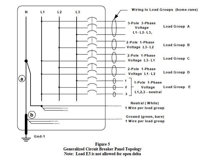
This voltage distribution concept shows that voltages are distributed to various loads throughout the facility with wiring groups, which are often multiple wires bundled together and encased in various synthetic skins.
For example, voltages supplied to a specific load group might be distributed with a “12-3 w/Gnd” UF cable. This is an underground cable containing 4 each number 12 gauge wires; a white wire used only as neutral, a red supply wire, a black supply wire, and a bare (or green) wire used only as ground. Wiring groups, which distribute voltage to specific loads are often refer to as “home-runs”. Each home-run contains colored supply line wires (black, red, etc) for the appropriate L1, L2, L3 phase voltage(s) needed and a neutral wire, always white, and generally a green or bare copper wire, for grounding. Ground wires are never allowed to conduct any load current. Each supply phase in a home-run wire group is circuit breaker protected. In addition, both the white neutral (return) wire and the ground wire are continuous and return to points (a) and (b) in the circuit breaker panel, see Figure 5. One could think of the white neutral wires and ground wires emanating from the panel box like spokes on a wagon wheel. Note that;
- All home runs have their white neutral lines connected at point (a), which is connected to the utility company supply transformer neutral, Gnd-0.
- All home runs have their ground lines connected at point (b), which is connected to an earth ground Gnd-1 located at the distribution circuit breaker panel.
- In the circuit breaker panel, points (a) and (b) are connected resulting in connecting earth (Gnd-1) to the white neutral wire. This is a NEC requirement.
Resulting Situation:
All neutral (return) currents for all the loads throughout the total facility are vector summed at point (a) in the main distribution circuit breaker panel. The balance of this neutral current sum must then return to the utility company’s supply transformer neutral, shown as Gnd-0 in Figures 1,2, 3, and 4. The return path for this net neutral current is the neutral wire installed by utility companies and/or electrical contractors.
The utility company has sized and installed this neutral wire to handle return load currents from a customer’s facility. Since all the neutral wires at (a) and all the ground wires at Gnd-1 (b) are connected in the circuit breaker panels, there are additional parallel return paths for this net neutral current distributed throughout structural framing steel, concrete re-bars, plumbing pipes, and bare earth. All these paths lead back to Gnd-0 at the supply transformers.
Figure 6 illustrates this situation using two additional points (w) and (x) connected to “grounds” somewhere within the facility.
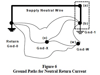
The network of ground return paths is very complex and impossible to accurately model. Moreover, it is time dependent, affected by new construction, weather, corrosion, etc. If the main supply neutral wire and all its connections have a combined impedance (Zg) much smaller than the parallel web of ground paths, then that portion of the return current, which splits (Kirchhoff’s Current Law) into these ground paths can be neglected. Consequently, voltage drops (Ig*Zg) associated with this small current can be neglected as well.
Interesting Phenomena
The following are sample situations, which can arise regarding unexpected voltages on ground lines. Equally surprising phenomenon can occur on supply lines L1, L2, and L3; however the focus of this application note is on ground lines and so “surprises” on L1, L2, and L3 will not be illustrated.Case 1
Given a small 30 horsepower, 240 volt, 60cycle, 3-phase, 4-wire, wye connected induction motor used in a HVAC system as an air handler. Assume that the motor’s average running point has an efficiency of 87% and a power factor of 0.93. This operating situation requires 66.5 amps of line current from each line (L1, L2, L3). The vector sum of these currents in the neutral line is zero.
If for whatever the reasons; fire, heat, loose connections, etc, one of the motor’s 3-phase windings is lost (opens); an unbalanced 3-phase system is created. For this situation, one line current drops to zero and 66.5 amps flows in the other two supply lines. Surprisingly, the vector sum of these currents in the neutral wire now suddenly jumps from zero to 66.5 amps. WOW, what a surprise. This situation will not prevail, the motor’s speed, efficiency, power factor, and other operating characteristics change and hopefully, the motor control will shut the motor down. Nonetheless, for a moment there was a large surge of current in the neutral line.
The flow path for this sudden change in neutral line current is from point (a) in the circuit breaker panel (Figures 5, 6) to the utility’s supply return point, Gnd-0. Figure 6 clearly indicates that the exact “return” path for this sudden change in current is essentially impossible to analyze; however, we do know that there will be a sudden change in the voltage at “ground” points Gnd-1, Gnd-X, and Gnd-W. Instrumentation equipment and associated sensors may be damaged by this surge.
Case 2
If the supply neutral line is open (broken) to an unbalanced 3-phase wye load, the wye connection point is forced to some non-zero voltage.
Consider any balanced 3-phase wye connected motor where the supply neutral return line is open (broken) and one phase winding has failed open. The wye connection point becomes [Vline-line ÷ (2x√3)] volts, which is 69.3 volts for a 240 line-to-line voltage system. Often, a 3-phase 4-wire motor’s wye connection point is connected to its frame, which is loosely connected to building ground. In this case, “ground” is suddenly forced to 69.3 volts. This situation may not prevail, since the motor’s operating characteristics change and motor safety controls should shut down the motor. Nonetheless, for a moment there is a sudden voltage surge on “ground”. This could be hazardous to personnel and could damage instrumentation equipment and sensors.
Note: The single-phase 120-volt loads shown in Figure 5 as Group E form a composite 3-phase wye connected unbalanced load where the wye connection point is the (a)-(b) connection. Losing the supply neutral return wire will cause point (b) and all the connected earth grounds to support an unexpected surge in current due to an attempted sudden rise in voltage at point (b). This is analogous to the failed motor in the above Case 2.
Interested readers are encouraged to visit Dataforth’s web site and download Application Note AN109 (Ref. 5) to revisit AC calculations for single and three phase systems.
Case 3
Personal computers, laser jet printers, scanners, copiers, and most modern electronics are designed with internal switching power supplies. These type supplies are inexpensive, more efficient, and smaller than older supply technology. Unfortunately, the supply line input currents required by these type supplies are complex pulse waveforms, which all vector sum at point (a) in circuit breaker panels, see Figure 5. Figure 7 illustrates this switching power supply phenomenon.
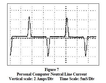
The data in Figure 7 was taken with a Tektronix Digital Storage Scope (DSO) using a current transformer (CT) type probe on the 115-volt supply neutral (white) wire. These test data show that a single computer can generate current spikes with amplitudes of almost 4 amperes on the neutral line. Consider an office facility with several dozen PCs, printers, copiers, and scanners. All the neutral current pulses from these devices vector sum at point (a) in the main circuit breaker panel. See Figures 5, 6. Clearly these spikes can create sudden, unexpected, and undesirable voltages at all the ground points.
Case 4
Of all the undesirable noise generating phenomena, perhaps electrical storms are the most detrimental and most difficult to analyze. Voltage distribution networks, including their associated web of grounding have multiple geometric wiring “closed loop” configurations capable of responding to the electrical storm induced mobile charges. No single unified model exists for the exact induction mechanism, which creates these electrical surges in voltage and currents. Lighting bolts contain “zillions” of joules of energy capable of displacing “gazillion” charged particles, which must distribute themselves to reestablish steady state conditions. The resulting voltage, electromagnetic fields, and moving charges can have horrendous magnitudes.
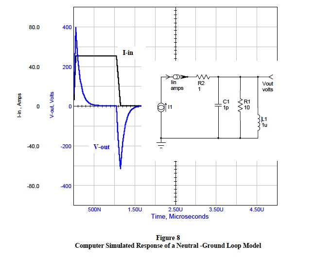
As an example, Figure 8 illustrates the response of a “ground loop” energized by a sudden 50-ampere current surge. As shown above, current surges in this range are possible without electrical storms; although, electrical storms are more likely responsible. In this example, resistive, capacitive, and inductive lumped elements were used to model a neutral return line and an associated ground loop. The values used are well within the range of possibilities. Surprisingly, the voltage generated by this redistribution of charge (current surge) is approximately 700 volts peak to peak. The results will be more severe with an electrical storm direct hit. Will your signal conditioning modules and field sensor electronics take this abuse?
Prevention and Protection Method
It is not possible to protect all facilities from all possible natural phenomenon and potential accidents such as electrical storms, earthquakes, plant fires, and employee’s careless work habits. Nonetheless, using proper grounding and isolation techniques will go a long way toward eliminating instrumentation errors caused by these situations.Dataforth is well aware of instrumentation problems caused by noisy supplies with bad grounds and has developed a full line of isolated signal conditioning modules with filtered inputs, which are overload, surge, and transient protected. These isolated signal conditioning instrumentation modules provide isolation from both power supply lines and ground lines; thus eliminating many of the problems associated with “bad” grounds and “noisy” supply lines. In addition, the field side signals are isolated from the computer (reading) side.
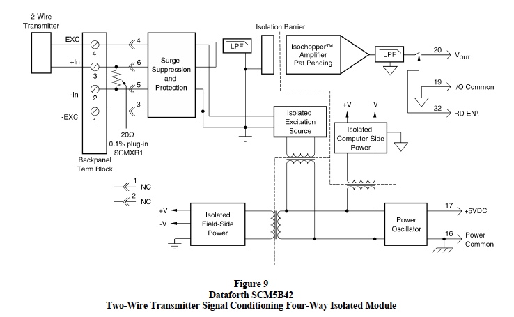
Figure 9 shown below is an example of a Dataforth unique “4-way” isolated signal-conditioning module. Note that this module is isolated from its input power (pins 16,17) and in addition;
- supplies isolated power to the field side electronics,
- supplies isolated power to the computer side electronics,
- supplies isolated excitation for field sensors, an
- isolates the signal path from the computer side electronics.
References
The reader is encouraged to visit Dataforth’s web site and explore their complete line of isolated signal conditioning modules and related application notes, see references shown below.- Application Notes AN502, AN507, AN508, and AN109 (in Application Notes Library)
- SCM5B42 Two-Wire Transmitter Signal Conditioning Module
- National Electric Code controlled by National Fire Protection Agency, NFPA
Was this content helpful?
Thank you for your feedback!