


an122: Introduction to PID Control
Application Note
Preamble
PID controllers are used in most automatic process control applications in industry. They can regulate flow, temperature, pressure, level, and many other industrial process variables. This Application Note reviews the design of PID controllers and explains the P, I, and D control modes used in them.Manual Control
Without automatic controllers, all regulation tasks have to be done manually. For example: To keep constant the temperature of water discharged from an industrial gasfired heater, an operator has to watch a temperature gauge and adjust a fuel gas valve accordingly (Figure 1). If the water temperature becomes too high for some reason, the operator has to close the gas valve a bit – just enough to bring the temperature back to the desired value. If the water becomes too cold, he has to open the gas valve.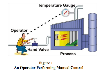
Feedback Control
The control task done by the operator is called feedback control, because the operator changes the firing rate based on feedback that he gets from the process via the temperature gauge. Feedback control can be done manually as described here, but it is commonly done automatically, as will be explained in the next section.The operator, valve, process, and temperature gauge form a control loop. Any change the operator makes to the gas valve affects the temperature, which is fed back to the operator, thereby closing the loop.
Automatic Control
To relieve the operator from the tedious task of manual control, the control function can be automated with a PID controller. The following are required:- Install an electronic temperature measurement device
- Automate the valve by adding an actuator (and perhaps a positioner) to it so that it can be driven electronically
- controller, and connect it to the electronic temperature measurement and the automated control valve
A PID controller has a Set Point (SP) that the operator can set to the desired temperature. The Controller’s Output (CO) sets the position of the control valve. And the temperature measurement, called the Process Variable (PV), gives the controller its much-needed feedback. The process variable and controller output are transmitted via current, voltage, or digital signals (Figure 2).
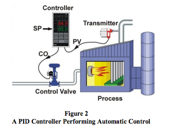
When everything is up and running, the PID controller receives the process variable signal, compares it to the set point, and calculates the difference between the two signals, also called the Error (E). Then, based on the error and the PID controller’s tuning constants, the controller calculates an appropriate controller output that sets the control valve to the right position for keeping the temperature at the set point. If the temperature should rise above its set point, the controller will reduce the valve position and vice versa.
PID Control
PID controllers have three control modes:- Proportional Control
- Integral Control
- Derivative Control
Proportional Control Mode
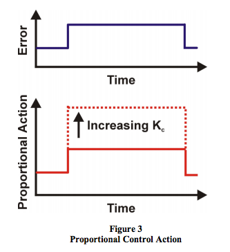
The proportional control mode is the main driving force in a controller. It changes the controller output in proportion to the error (Figure 3). If the error increases, the control action increases proportionally. This is very useful, since more control action is needed to correct large errors.The adjustable setting for proportional control is called the Controller Gain (Kc). A higher controller gain will increase the amount of proportional control action for a given error. If the controller gain is set too high the control loop will begin oscillating and become unstable. If the controller gain is set too low, it will not respond adequately to disturbances or set point changes.
 For most controllers, adjusting the controller gain setting
influences the amount of response in the integral and
derivative control modes. This is why the parameter is
called controller gain. However, there is one controller
design (called a parallel or independent gains algorithm)
in which adjusting the proportional gain does not affect
the other modes.
For most controllers, adjusting the controller gain setting
influences the amount of response in the integral and
derivative control modes. This is why the parameter is
called controller gain. However, there is one controller
design (called a parallel or independent gains algorithm)
in which adjusting the proportional gain does not affect
the other modes.
The Proportional-Only Controller
A PID controller can be configured to produce only a proportional action by turning off the integral and derivative modes. Proportional controllers are simple to understand and easy to tune. The controller output is simply the control error times the controller gain, plus a bias (Figure 4). The bias is needed so that the controller can maintain a non-zero output while the error is zero (process variable at set point).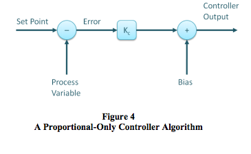
The use of proportional-only control has a large drawback – offset. Offset is a sustained error that cannot be eliminated by proportional control alone. For example, let’s consider controlling the water level in the tank in Figure 5 with a proportional-only controller. As long as the flow out of the tank remains constant, the level will remain at its set point.
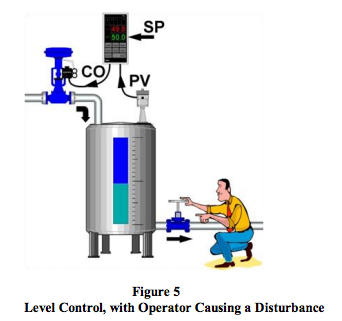
But, if the operator should increase the flow out of the tank, the tank level will begin to decrease due to the imbalance between inflow and outflow. While the tank level decreases, the error increases and the proportional controller will increase the controller output proportionally to this error. Consequently, the valve controlling the flow into the tank opens wider and more water flows into the tank.
As the level continues to decrease, the error increases and valve continues to open until it gets to a point where the inflow again matches the outflow. At this point the tank level (and error) will remain constant. Because the error remains constant our P-controller will keep its output constant and the control valve will hold its position. The system now remains in balance, but the tank level remains below its set point. This remaining sustained error is called Offset.
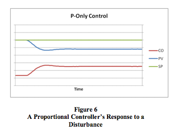
Figure 6 shows the effect of a sudden decrease in fuel gas pressure to the process heater described earlier, and the response of a p-only controller. The decrease in fuel gas pressure reduces the firing rate and the heater outlet temperature decreases. This creates an error to which the controller responds. However, a new balance point between control action and error is found and the temperature offset is not eliminated by the proportional controller.
Under proportional-only control, the offset will remain present until the operator manually changes the bias on the controller’s output to remove the offset. It is said that the operator manually resets the controller.
Integral Control Mode
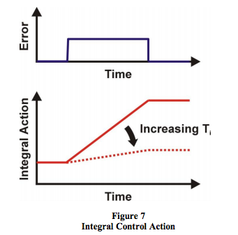
The need for manual reset, as described above, led to the development of automatic reset or the integral control mode, as it is known today. The function of the integral control mode is to increment or decrement the controller’s output over time to reduce the error, as long as there is any error present (process variable not at set point). Given enough time, the integral action will drive the controller output until the error is zero.If the error is large, the integral mode will increment/ decrement the controller output at a fast rate; if the error is small, the changes will be slow. For a given error, the speed of the integral action is set by the controller’s integral time setting (Ti). A large value of Ti (long integral time) results in a slow integral action, and a small value of Ti (short integral time) results in a fast integral action (Figure 7). If the integral time is set too long, the controller will be sluggish; if it is set too short, the control loop will oscillate and become unstable.
Most controllers, including the MAQ®20, use integral time (Ti) in minutes as the unit of measure for integral control, but some use integral time in seconds. A few controllers, typically ones with the parallel algorithm, use integral gain (Ki) in repeats per minute. The parallel algorithm is also available in the MAQ®20.
Proportional + Integral Controller
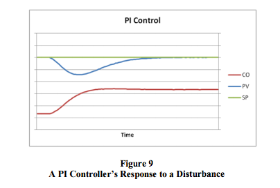
Commonly called the PI controller, the proportional + integral controller’s output is made up of the sum of the proportional and integral control actions (Figure 8).Compared to Figure 6, it is clear how integral control continues to drive the controller output until it has eliminated all offset.
Derivative Control Mode
The third control mode in a PID controller is the derivative control mode. Derivative control is rarely used in controlling processes, but it is used often in motion control. For process control, it is not absolutely required, is very sensitive to measurement noise, and it makes trialand-error tuning more difficult. Nevertheless, using the derivative control mode of a controller can make certain types of control loops respond a little faster than with PI control alone (temperature control is a typical application for PID control).The derivative control mode produces an output based on the rate of change of the error (Figure 10). Because of this, derivative mode was originally called rate. The derivative mode produces more control action if the error changes at a faster rate. If there is no change in the error, the derivative action is zero. The derivative mode has an adjustable setting called Derivative Time (Td). The larger the derivative time setting, the more derivative action is produced. A derivative time setting of zero effectively turns off this mode. If the derivative time is set too long, oscillations will occur and the control loop will run unstable.
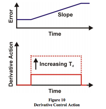
Two units of measure are used for the derivative setting of a controller: minutes and seconds.
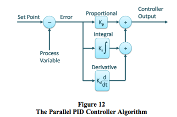
Proportional + Integral + Derivative Controller
Commonly called the PID controller, the Proportional + Integral + Derivative controller’s output is made up of the sum of the proportional, integral, and derivative control actions. Figure 11 shows the noninteractive PID controller algorithm and Figure 12 shows the parallel controller algorithm. These are both supported in the MAQ®20 system.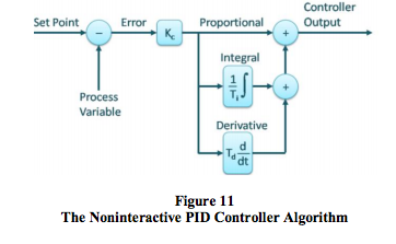
The derivative mode of the PID controller provides more control action sooner than is possible with P or PI control. This reduces the effect of a disturbance and shortens the time it takes for the level to return to its set point (Figure 13).
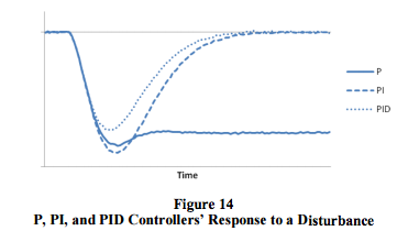
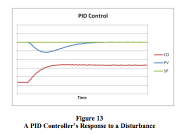 Figure 14 compares the recovery under P, PI, and PID
control of the process heater outlet temperature after a
sudden change in fuel gas pressure as described above.
Figure 14 compares the recovery under P, PI, and PID
control of the process heater outlet temperature after a
sudden change in fuel gas pressure as described above.
Conclusion
The PID controller is the workhorse of modern process control systems. The proportional, integral, and derivative control modes each fulfill a unique function. Proportional and integral control modes are essential for most control loops, while derivative is useful only in some cases. PID control algorithms come in different designs, and the MAQ®20 supports the most common noninteractive algorithm, as well as the parallel algorithm.This PID algorithm versatility makes the MAQ®20 extremely powerful and adaptable to wide ranging process control applications including:
- Test and Measurement
- Factory and Process Automation
- Machine Automation
- Military and Aerospace
- Oil and Gas
- Environmental Monitoring
Learn more about the MAQ®20 Data Acquisition and Control System
Was this content helpful?
Thank you for your feedback!