


an202: LDM485 to LDM485 to Other RS-485 Devices Configuration
Application Note
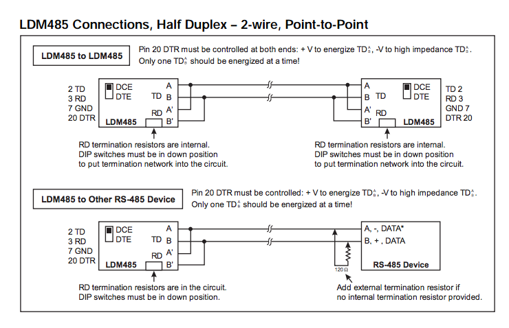
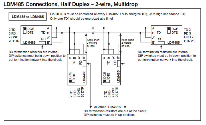
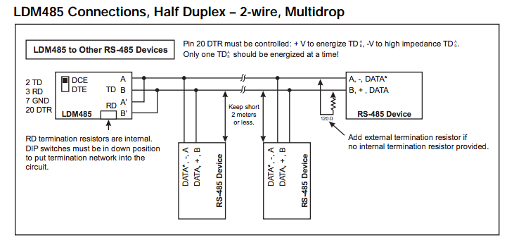
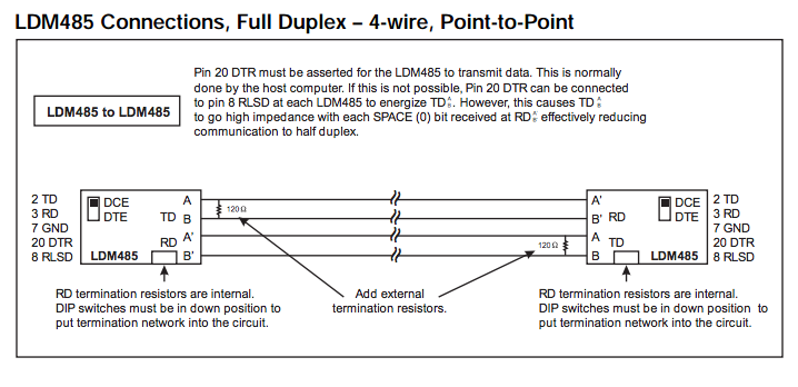
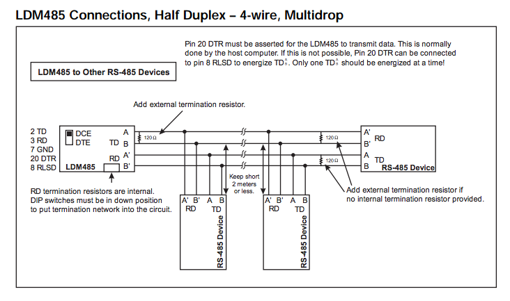
General Notes on Termination:
For LDM485 or other RS-485 device at the extr or LDM485 or other RS-485 device at the extreme ends of the line:The need for termination depends on data rate, line length, cable electrical characteristics and environment, and if applicable, the number of multidropped devices. This is best determined by switching in or out each termination network for most reliable data transfer.
For LDM485, some terminations may need to be added externally
For TD (Transmit Data), 120Ω may be needed across the lines in the 4-wire configurations.
For RS-485 devices other than the LDM485, termination networks may be need to be added externally.
For TD (Transmit Data), 120Ω across the lines is standard.
For RD (Receive Data), 120Ω across the lines may suffice.
However, some cases may need line bias resistors as well. The line bias resistors hold the true data line (B', +, DATA) at least 0.2V more positive than the inverted data line (A', –, DATA*) in the MARK (idle) state. The network will consist of a 3.3KΩ pullup resistor connected to +5.0V at one end to the true data line and the 120Ω resistor at the other end. Then a 3.3KΩ pull-down resistor connected to Return at one end to the inverted data line and the 120Ω resistor at the other end. If +5V and/or Return are not available externally, you may have to contact the manufacturer to find out how to access these internally. Another alternative is to install your own +5V power supply and connect its negative terminal to the RS-485 device's RS-485 Return. Also, if the RS- 485 circuits are isolated, use an isolated output power supply.
Was this content helpful?
Thank you for your feedback!