


an508: Protecting Signal Lines Against EMI
Application Note
In todays dynamic industrial environments, electronic devices, signal and
power wiring, and other electrical plant/process equipment often interact to
create noise or electromagnetic interference (EMI) problems which can
degrade critical measurement and control signals. Proper grounding and
shielding techniques can help reduce or eliminate these problems and maintain
signal integrity.
Three basic elements are required in order for a noise problem to exist; 1.) a noise source to generate the noise, 2.) a receiving device which is affected by the noise, and 3.) a coupling channel between the source and receptor. The objective in electromagnetic compatibility is to minimize, divert, or eliminate one of the three elements necessary for a noise problem.
An easy and effective way to minimize capacitively coupled interference is to use cable shielding. The shield is a Gaussian or equi-potential surface on which electric fields can terminate and return to ground without affecting the internal conductors.
Shielding is only effective against electric fields if it provides a low impedance path to ground. A floating shield provides no protection against interference. There is still a small capacitance between the noise source and conductor due to imperfections in the shield, holes in a braided shield, and, most importantly, due to the length of conductor extending beyond the shield. Attention must be paid to these remaining parasitics to avoid leaky shields.
The correct place to connect an electrostatic shield is at the reference potential of the circuitry contained within the shield. This point will vary depending upon whether the source and receiver are both grounded or whether one or the other is floating. It is important to ground the shield at only one point to ensure that ground currents do not flow through the shield. In most applications, the shield ground should not be at a voltage with respect to the reference potential of the circuitry. If it is, then this voltage can be coupled to the shielded conductor. The exception is when using guard shields, where the shield is intentionally held at a potential to prevent current flow in an unbalanced source impedance. Guard shields are normally used only in extremely sensitive applications or when high common-mode rejection is required.
The capacitance between two conductors is inversely proportional to the distance between them. Therefore, another simple way to reduce capacitive coupling is to increase the distance between the victim cable and the source cable. It is always a good idea to route noisy cables such as power input wiring, motor control wiring, and relay control wiring separate from quiet cables such as analog I/O lines, digital I/O lines, or LAN connections.
Figure 2 shows a magnetically coupled noise model analogous to the one presented earlier for capacitively coupled noise. Examination of the two models shows that the primary means of noise coupling can be determined by changing the signal source impedance, Rsignal. If Rsignal is reduced, capacitively coupled noise will decrease while magnetically coupled noise will increase.
Magnetic coupling is much more difficult to reduce than capacitive coupling because magnetic fields can penetrate conductive shields. Two types of loss, reflection and absorption, characterize how a shield works. Reflection loss is related to the ratio between the electromagnetic wave impedance and the shield impedance. Absorption loss is directly proportional to shield thickness and inversely proportional to shield material skin depth. It is highest at high frequencies and falls rapidly at low frequencies.
Fortunately, there are other ways to reduce magnetically coupled interference besides shielding. The voltage induced in a single turn of wire by the magnetic field lines which cut the loop can be derived from Faradays Law.
Making the general assumptions that the flux density (B) is sinusoidally time varying, as it would be for AC power line currents, and that B is constant over the area (A) of the loop, the following expression is obtained;

Here, B is the value of the flux density in Gauss, A is the area of the loop cut by the magnetic field lines in cm2, and θ is the angle between the two (Figure 3).
These three parameters are all under the control of the system designer. The magnetic field can be reduced by separating the source of the field from the receiving loop or by twisting the source wires. Loop area can be reduced by routing the conductors which form the loop closer together or by reducing the length of the conductors.
Solid shields provide the best theoretical noise reduction solutions but they are more difficult to manufacture and apply. Most cables are instead shielded with a braid for improved flexibility, strength, and ease of termination. Braided shields are less effective than solid shields because they only provide between 60% and 98% coverage of the cable. Decreased effectiveness is more prevalent at high frequencies where the holes in the braid are large compared to a wavelength. For maximum shielding, reliability, and ease of use, cables with combined shields are available which use both a solid layer and a braided layer.
Proper grounding is dependent upon many factors such as the frequencies and impedances involved, the length of cabling required, and safety issues. When designing a ground or troubleshooting a ground problem, it is first necessary to determine where the current is flowing. When several kinds of grounds coexist, the current may not return by the assumed path.
The most desirable type of ground for low frequency applications is the singlepoint ground. Two examples are shown in Figure 4. The series connection, or daisy chain, should be avoided when sensitive circuitry or cabling is involved because return currents from the three circuits flow through the common ground impedances linking the circuits. The ground potential of circuit 1 is not only determined by its return current through impedance Z1 but also by the return currents from circuits 2 and 3 through the same impedance. This effect is called common-impedance coupling and is a primary means of noise coupling.
The preferred ground is the parallel connection. It is usually more difficult and more costly to implement because of the amount of wiring involved. Determine first the circuit common-impedance coupled noise immunity when choosing between these ground configurations. Most systems use a combination of both topologies.
A popular method of isolation involves the use of signal conditioners based on transformers or optical couplers. In either case the common-mode noise voltage appears across the isolation device internal to the signal conditioner. Noise coupling is now reduced to the parasitic capacitance across the isolation barrier. Typical coupling capacitance in a opto-coupler is 2pF, or 0.5pF for shielded devices. Coupling can be further reduced with the use of LEDs, photodiodes, and fiber-optic cables. Faraday shielding can also be used in transformers to reduce coupling. Optical couplers are primarily used for digital signals because their linearity is not always suitable for use in analog circuits.
Three basic elements are required in order for a noise problem to exist; 1.) a noise source to generate the noise, 2.) a receiving device which is affected by the noise, and 3.) a coupling channel between the source and receptor. The objective in electromagnetic compatibility is to minimize, divert, or eliminate one of the three elements necessary for a noise problem.
Capacitive Coupling
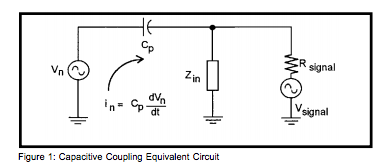
Any piece of plant equipment or wiring can develop an electric charge, or potential, which can be expressed as a voltage. If this charge changes, then a changing electric field is generated which can couple capacitively to other equipment or wiring. Capacitively coupled noise can be modeled as a current as shown in Figure 1. This type of noise is dominant when a circuit or termination has a high impedance because the noise voltage generated at the receiver is the noise current, in, times the receiver impedance, Zin.
An easy and effective way to minimize capacitively coupled interference is to use cable shielding. The shield is a Gaussian or equi-potential surface on which electric fields can terminate and return to ground without affecting the internal conductors.
Shielding is only effective against electric fields if it provides a low impedance path to ground. A floating shield provides no protection against interference. There is still a small capacitance between the noise source and conductor due to imperfections in the shield, holes in a braided shield, and, most importantly, due to the length of conductor extending beyond the shield. Attention must be paid to these remaining parasitics to avoid leaky shields.
The correct place to connect an electrostatic shield is at the reference potential of the circuitry contained within the shield. This point will vary depending upon whether the source and receiver are both grounded or whether one or the other is floating. It is important to ground the shield at only one point to ensure that ground currents do not flow through the shield. In most applications, the shield ground should not be at a voltage with respect to the reference potential of the circuitry. If it is, then this voltage can be coupled to the shielded conductor. The exception is when using guard shields, where the shield is intentionally held at a potential to prevent current flow in an unbalanced source impedance. Guard shields are normally used only in extremely sensitive applications or when high common-mode rejection is required.
The capacitance between two conductors is inversely proportional to the distance between them. Therefore, another simple way to reduce capacitive coupling is to increase the distance between the victim cable and the source cable. It is always a good idea to route noisy cables such as power input wiring, motor control wiring, and relay control wiring separate from quiet cables such as analog I/O lines, digital I/O lines, or LAN connections.
Inductive Coupling
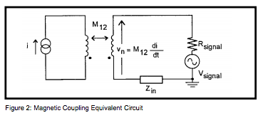
When a cable carries current, a magnetic field is generated. The direction of this magnetic field for current flowing in a long straight wire can be visualized using the right-hand rule. With the right-hand thumb pointed in the direction of the current flow, the fingers will show the direction of magnetic field lines. Imagine the complicated magnetic fields which exist near heavy electric machinery or where many cables are routed in a common tray. Lenzs Law states that currents can be made to flow in conductors by moving them through a magnetic field. Similarly, a changing magnetic field will induce currents in a stationary conductor which is in the field. Since most wiring is fixed in place, varying currents are the usual cause of magnetic coupling.Figure 2 shows a magnetically coupled noise model analogous to the one presented earlier for capacitively coupled noise. Examination of the two models shows that the primary means of noise coupling can be determined by changing the signal source impedance, Rsignal. If Rsignal is reduced, capacitively coupled noise will decrease while magnetically coupled noise will increase.
Magnetic coupling is much more difficult to reduce than capacitive coupling because magnetic fields can penetrate conductive shields. Two types of loss, reflection and absorption, characterize how a shield works. Reflection loss is related to the ratio between the electromagnetic wave impedance and the shield impedance. Absorption loss is directly proportional to shield thickness and inversely proportional to shield material skin depth. It is highest at high frequencies and falls rapidly at low frequencies.
Fortunately, there are other ways to reduce magnetically coupled interference besides shielding. The voltage induced in a single turn of wire by the magnetic field lines which cut the loop can be derived from Faradays Law.
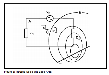
Making the general assumptions that the flux density (B) is sinusoidally time varying, as it would be for AC power line currents, and that B is constant over the area (A) of the loop, the following expression is obtained;
Here, B is the value of the flux density in Gauss, A is the area of the loop cut by the magnetic field lines in cm2, and θ is the angle between the two (Figure 3).
These three parameters are all under the control of the system designer. The magnetic field can be reduced by separating the source of the field from the receiving loop or by twisting the source wires. Loop area can be reduced by routing the conductors which form the loop closer together or by reducing the length of the conductors.
Twisted Pairs
The simplest way to reduce magnetically induced interference is to use twisted pair wires. This applies both for shielded and unshielded cables and for interference caused by shield currents or from other sources. Twisting the wires forces them close together, reducing the loop area and therefore the induced voltage. Since the currents are flowing in minimum loop areas, magnetic field generation is also reduced. The effectiveness of twisted pair wire increases with the number of twists per unit length.Shielding
Many potentially effective shields can be destroyed by improper termination of the shields to ground. A low impedance path to ground is essential in order to realize maximum shielding benefits. Pigtail connections from a shield to ground have inductance, resulting in an impedance which increases with frequency. This type of connection will work at frequencies below 10KHz but it will cause problems at higher frequencies. The use of short connections with large crosssectional area minimizes the inductance of a pigtail, but the best connection is a 360°contact between the shield and connector or chassis.Solid shields provide the best theoretical noise reduction solutions but they are more difficult to manufacture and apply. Most cables are instead shielded with a braid for improved flexibility, strength, and ease of termination. Braided shields are less effective than solid shields because they only provide between 60% and 98% coverage of the cable. Decreased effectiveness is more prevalent at high frequencies where the holes in the braid are large compared to a wavelength. For maximum shielding, reliability, and ease of use, cables with combined shields are available which use both a solid layer and a braided layer.
Grounding
In industrial environments, ground systems carry signal and power return currents, form references for analog and digital circuits, bleed off charge buildup, and protect people and equipment from faults and lightning. Any current flow in a ground system can cause differences in potential. Lightning strikes or other transient events can generate hundreds to thousands of volts of potentialdifference. A ground system must be considered from the beginning in order for the circuit or system to work in the intended environment and pass interference, emissions, and safety requirements.Proper grounding is dependent upon many factors such as the frequencies and impedances involved, the length of cabling required, and safety issues. When designing a ground or troubleshooting a ground problem, it is first necessary to determine where the current is flowing. When several kinds of grounds coexist, the current may not return by the assumed path.
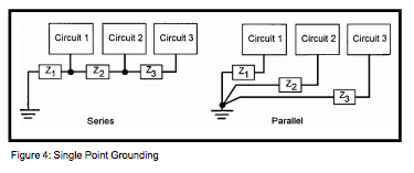
The most desirable type of ground for low frequency applications is the singlepoint ground. Two examples are shown in Figure 4. The series connection, or daisy chain, should be avoided when sensitive circuitry or cabling is involved because return currents from the three circuits flow through the common ground impedances linking the circuits. The ground potential of circuit 1 is not only determined by its return current through impedance Z1 but also by the return currents from circuits 2 and 3 through the same impedance. This effect is called common-impedance coupling and is a primary means of noise coupling.
The preferred ground is the parallel connection. It is usually more difficult and more costly to implement because of the amount of wiring involved. Determine first the circuit common-impedance coupled noise immunity when choosing between these ground configurations. Most systems use a combination of both topologies.
Ground Loops
Ground loops exist in a system when there are multiple current return paths or multiple connections to earth ground. Current flowing in a ground loop generates a noise voltage in the circuit. The most obvious way to eliminate the loop is to break the connection between the transducer and ground or between the receiver and ground. When this is not possible, isolation of the two circuits is a universal way to break the loop. Isolation prevents ground loop currents from flowing and rejects ground voltage differences.A popular method of isolation involves the use of signal conditioners based on transformers or optical couplers. In either case the common-mode noise voltage appears across the isolation device internal to the signal conditioner. Noise coupling is now reduced to the parasitic capacitance across the isolation barrier. Typical coupling capacitance in a opto-coupler is 2pF, or 0.5pF for shielded devices. Coupling can be further reduced with the use of LEDs, photodiodes, and fiber-optic cables. Faraday shielding can also be used in transformers to reduce coupling. Optical couplers are primarily used for digital signals because their linearity is not always suitable for use in analog circuits.
Was this content helpful?
Thank you for your feedback!