


RTD, Resistance Temperature Detector
Tech Note
Preamble
Temperature measurements are perhaps the oldest known measurements. One of the most linear, stable, and reproducible temperature sensors is the Platinum RTD, Resistance Temperature Detector. The RTDs resistance vs temperature characteristics are stable, reproducible, and have a near linear positive temperature coefficient from 200 to 800 °C. These attributes establish RTDs as a de-facto industry standard. Temperature is determined by measuring resistance and then using the RTDs R vs T characteristics to extrapolate temperature.Typical elements used for RTDs are Nickel (Ni), Copper (Cu), and Platinum (Pt). By far the most common are the 100-ohm or 1000-ohm Platinum RTDs, sometimes referred to as PRTs, Platinum Resistance Thermometers.
Historically, RTDs have been specified by their value at zero °C R(0), and a positive temperature coefficient alpha, which is averaged from 0 to 100 °C. Over the years, both American and European RTD standards have been developed to ensure that RTDs are interchangeable from manufacturer to manufacturer without any significant loss in accuracy. Platinum RTDs have been defined by standards such as; DIN 43760 (BS1904), IEC 751-1983, and JIS C1604. These standards specify RTD parameters, which include; R(0), alpha, tolerance classifications, and coefficients in the Callendar-Van Dusen mathematical model of resistance versus temperature.
In the late 1990s, the standards community published new standards in an effort to define a single definition for Platinum RTDs. Standards ASTM 3711 and IEC 60751 represent the new Platinum RTD standards.
Basics of Temperature Dependent Resistance
The fundamental concept of temperature dependent resistance in metal conductors is illustrated in the following section. Complex quantum mathematical derivation details have been omitted.Current flow in any material is the flow of charged particles per unit time. In metals, these particles are electrons. Metals are excellent conductors because their molecular structure has an abundance of electrons loosely coupled to their molecular nuclei and are, therefore, readily available to move.
Definitions:
- The unit of charge is defined by the Coulomb
- One ampere is defined to be a coulomb of charge flowing past a point in one second, coulomb/sec.
- An electron (defined by e) has a negative charge of 1.602E-19 coulombs. This means that there are 6.24E18 electrons in one coulomb of charge and that 1-ampere requires 6.24 billion billion electrons to travel past a point in one second.
An applied voltage (Vapplied) forces loose electrons to move at an average velocity, which creates a current given by:

Where:
- "e" is charge on an electron (1.6E-19 coulombs),
- "A" is wire area,
- "L" is wire length,
- "n" is electron density, (number per unit volume), and
- "μ" is mobility, an extremely complex term that relates how electrons interact with each other and with the wires molecular structure.

Where
 and is the familiar parameter "resistivity", which characterizes resistance of any given material. Note that since the electron charge .e. is a constant, resistance is completely dominated and controlled by the product of (n) electron density and (μ) electron mobility. For most metals over a rather large range of temperature, the (n x μ) product decreases with increasing temperature; this increases resistance and establishes a positive temperature coefficient. The number of electrons and their complex interactive behavior controls the resistance of materials.
The complex interactive behavior of billions of electrons scrambling down a wire under the influence of temperature and a forcing voltage creates a resistivity that is seldom linear over all temperature. However, Copper, Nickel, and Platinum do have near linear temperature coefficients over certain ranges of temperature and, therefore, are used in the manufacture of RTDs. Platinum is the most linear.
RTD Model
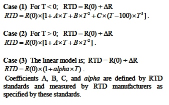
RTD standards, define Platinum resistance vs temperature behavior by the Callendar-Van Dusen equation, a non-linear mathematical model. These standards include; the RTD value at 0 °C, R(0), equation coefficients, and a temperature coefficient, alpha (α) defined from 0 to 100 °C. Alpha (α) can sometimes be used to establish a simple linear model for resistance vs temperature. In addition, different tolerance ranges identified as .classes. are included within the associated standard.s information. The Platinum RTD Callendar-Van Dusen non-linear model is a forth order polynomial for negative temperatures and a quadric for positive temperatures.Cases 1, 2, 3 below show models for the RTD in the general form of RTD = R(0) + ΔR, where ΔR is the temperature dependent part of the RTD.
Measuring Temperature with RTDs
Temperature measurements with RTDs first electronically measure the RTD resistance and then convert to temperature using the RTDs resistance vs temperature characteristics. There are numerous circuit topologies used to determine resistance. For example, Figure 1 illustrates a classic bridge configuration used for 3-wire RTD measurements.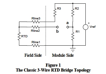
The voltage Vba in Figure 1 varies as RTD changes with temperature. For R1 = R2 = R3 = R(0), equal Rlines, and RTD defined as RTD = R(0) + ΔR then,
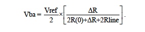
Typical bridge output voltages (as shown above) include line resistance and are non-linear.
Modern semiconductor technology facilitates resistance measurements with linear outputs and line resistances eliminate. For example, Figure 2 illustrates a 4-wire RTD configuration with current excitation.
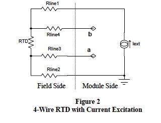
In Figure 2, Vba = Iext x [ R(0) +ΔR], which is a circuit linear output with line resistances eliminated. Note, this scheme does not require equal line resistances. Dataforth offers a 4-wire RTD module, the SCM5B35, which employs the scheme in Figure 2 including RTD vs T linearization and signal isolation.
Figure 3 illustrates another Dataforth modern circuit technique for measuring resistance of a 3-wire RTD given as RTD = R(0) + ΔR.
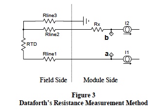
Given equal line resistances (a reasonable assumption for field cable), this measurement technique eliminates their effect. Moreover, R(0), the temperature independent resistance part of the RTD is removed.
If Rline3 = Rline2 = Rline1; Rx = R(0); I1 = I2= I; then Vba = ΔR x I, where ΔR is the temperature dependent resistance part of the RTD.
This voltage Vba is electronically scaled and linearized to represent the actual temperature.
Self Heating
Self-heating errors can arise when the excitation circuit drives RTD sensors at power levels exceeding the manufacture.s specification. For example, if the excitation current (I) in Figure 2 is 250 micro-amps, which is Dataforth.s value for 100 Ohm RTDs, and temperature is .50 °C (~80 Ω), then RTD power dissipation would be ~5 micro-watts. For industrial RTD sensors, current excitation less than 500 μA rarely cause self-heating errors. One should always check.Typical Dataforth Module
Figure 4 shows the topology layout of Dataforths DIN Rail mounted DSCA34 Linearized 2-or3-Wire RTD Input Signal Conditioning Module, which uses the above excitation method with isolation, surge protection, and linearization included.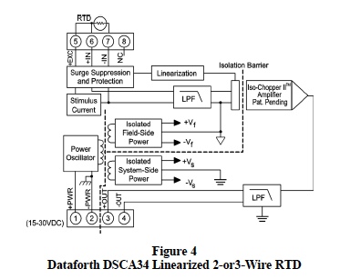
Dataforth provides a complete line of signal conditioning modules that include isolation, input protection, and linearization for a variety of industrial applications.
Was this content helpful?
Thank you for your feedback!