FAQ
What is the DC channel to channel isolation on SCM5B backpanels?
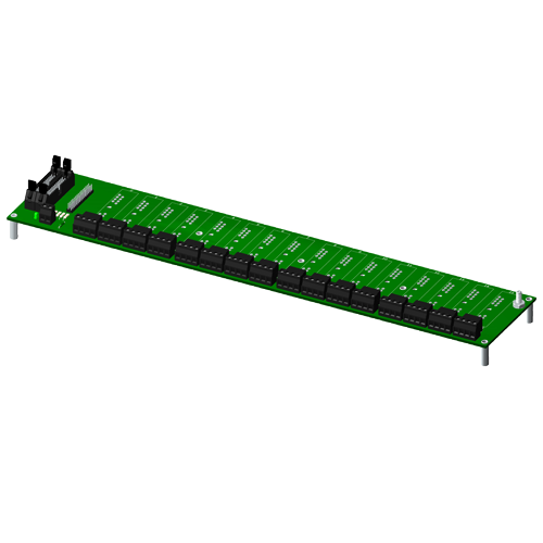
DC channel to channel isolation for all SCMPB backpanels is 2121 VDC.
Can Dataforth analog modules be used in high vibration environments? If so, what type of testing or certification was completed?
SCM5B, SCM7B, 8B SensorLex, and DSCA modules are well suited for use in high vibration environments. These modules and their associated accessories have undergone testing for random vibration, shock, and swept sine wave vibration. Details of each of these testing methods are provided below:
Random Vibration (Operating):
○ MIL-STD 202G, Method 214A, Condition 1
- Frequency Range: 50-2000Hz, flat spectrum
- Vibration Intensity: 7.56 Grms
- Duration: 10min/axis (X, Y, Z)
Shock (Operating):
○ MIL-STD-810F, Method 516.5
- Pulse Shape: Sawtooth
- Test Level: 30G
- Duration 11ms
- Orientation: +/-X, +/-Y, +/-Z
Swept Sine Vibration (Operating)
○ MIL-STD-810G, Method 514.6, modified
- Frequency Range: 10-2000Hz
- Vibration Intensity: 5Gp-p
- Sweep Rate: 1 octave/min
- Orientation: X, Y, Z
Declaration of conformity for the above-listed tests can be provided upon customer request. Please contact customer service if a copy of the declaration is needed.
Due to resource constraints on my computer, I'm unable to open the three dimensional CAD models provided on your website. Does Dataforth provide two demensional CAD models for download as well?
Two dimensional CAD models can be generated upon customer request. Please contact Customer Service for assistance.
Will a 2Vpp signal work with an SCM5B41-01?
Yes, as long as the peak voltage of this signal does not exceed 1V in the positive range or -1V in the negative range. Since the SCM5B series has a 1500Vrms CMR rating, this signal could also be measured on top of a much larger signal up to 1500Vrms, as long as the differential signal going into the input of the module is no higher than 1V or no lower than -1V.
What does it mean when an input module has for example a 3kHz bandwidth?
A 3kHz bandwidth on an input module means it can accept voltages from DC to 3000Hz. Any frequency higher than that and the signal will start to be attenuated by the filter at the input.
What does "Response time, 90% span" mean on the datasheet for my module?
Normally, a response time figure refers to how quickly a module's output can "respond" to a change in the input signal. "Response time, 90% span" refers to how fast a module can adjust its output when a step signal is applied at the input, where the magnitude of this step input is 90% of the input span of the module.
Can a signal conditioning modules be hot swapped?
Yes, any signal conditioning module series and MAQ20 I/O modules can be hot swapped. A minimal amount of signal settling time may result, but there will be no damage to the device.
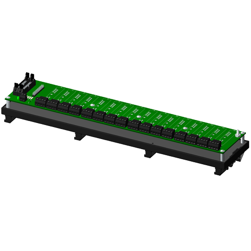
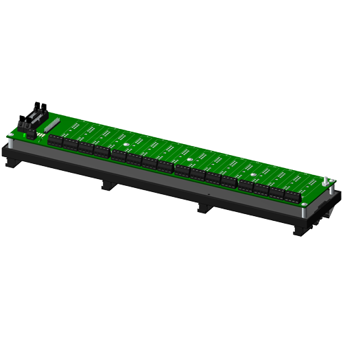
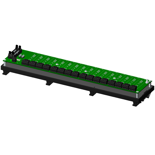
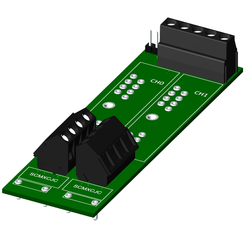
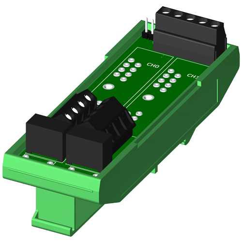
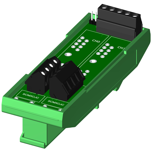
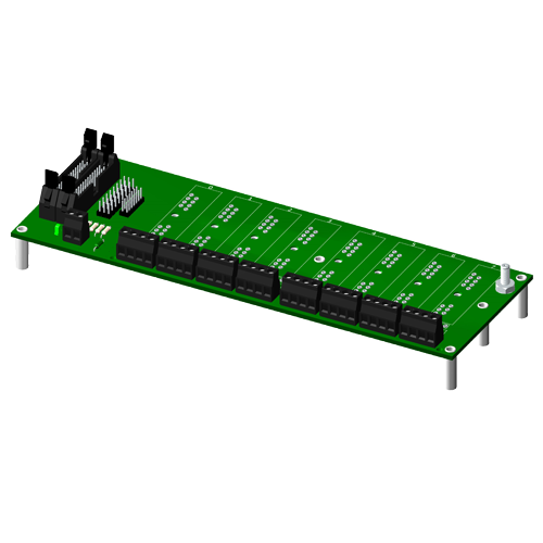
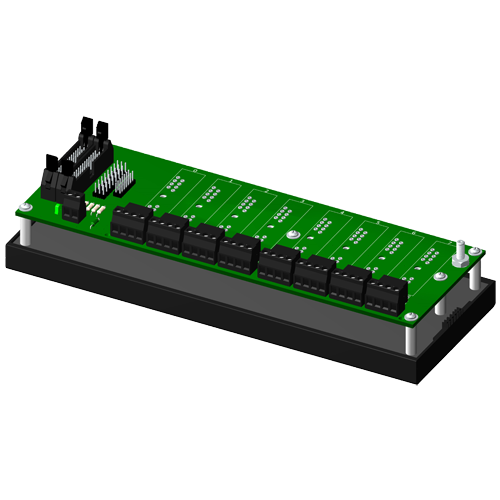
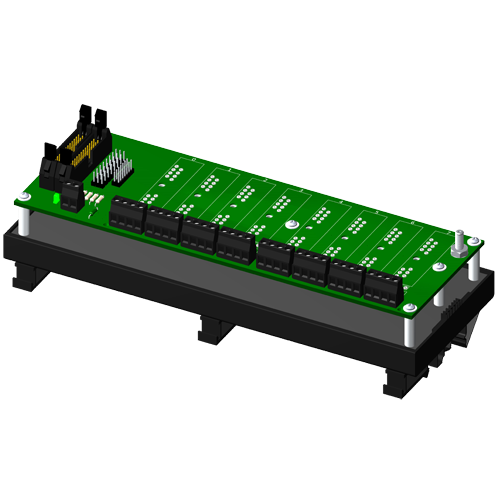
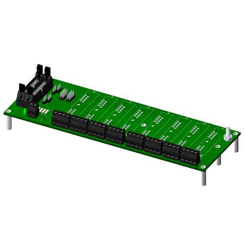
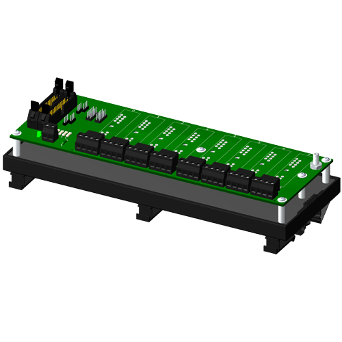
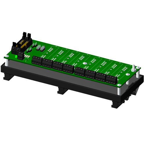
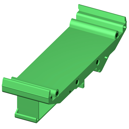
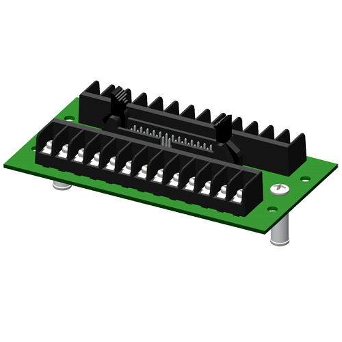
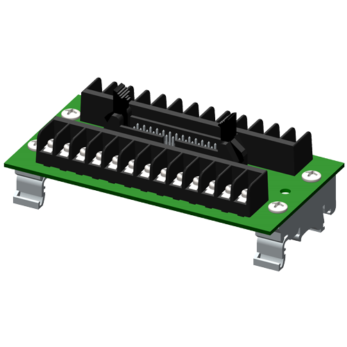
Can the DIN rail mounting hardware be easily removed from the SCMPB04?
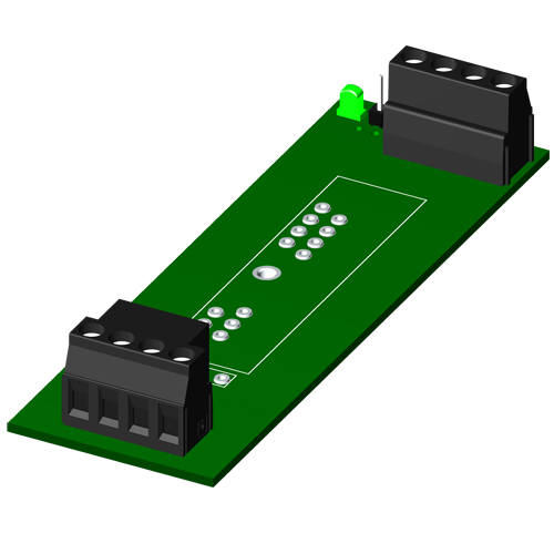
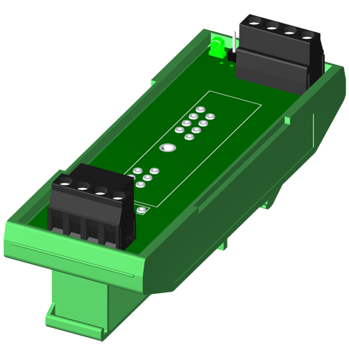
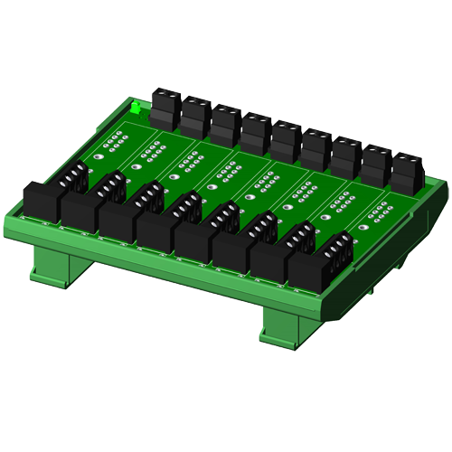
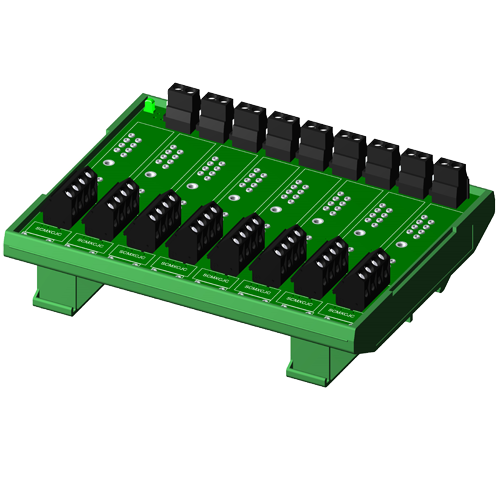
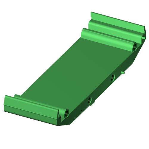
Yes, the DIN rail mounting hardware for the SCMPB04 can be easily detached and reattached from the board.
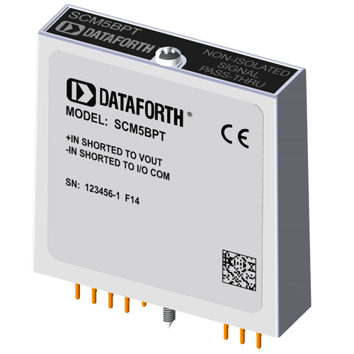
Where can I find the pinout of my SCM5B module?
Please see the SCM5B Module Dimensions and Pinouts link from the SCM5B section of our website: https://www.dataforth.com/catalog/pdf/scm5bdim.pdf
You can also find the module dimensions and pinouts in our product catalog.
What types of DIN rails does the DIN rail mounting of the SCMPB04 attach to?
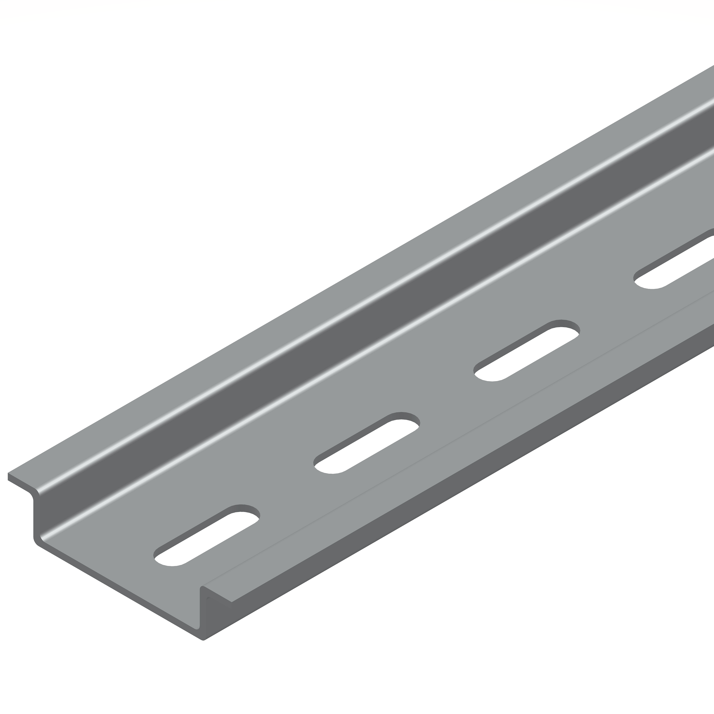
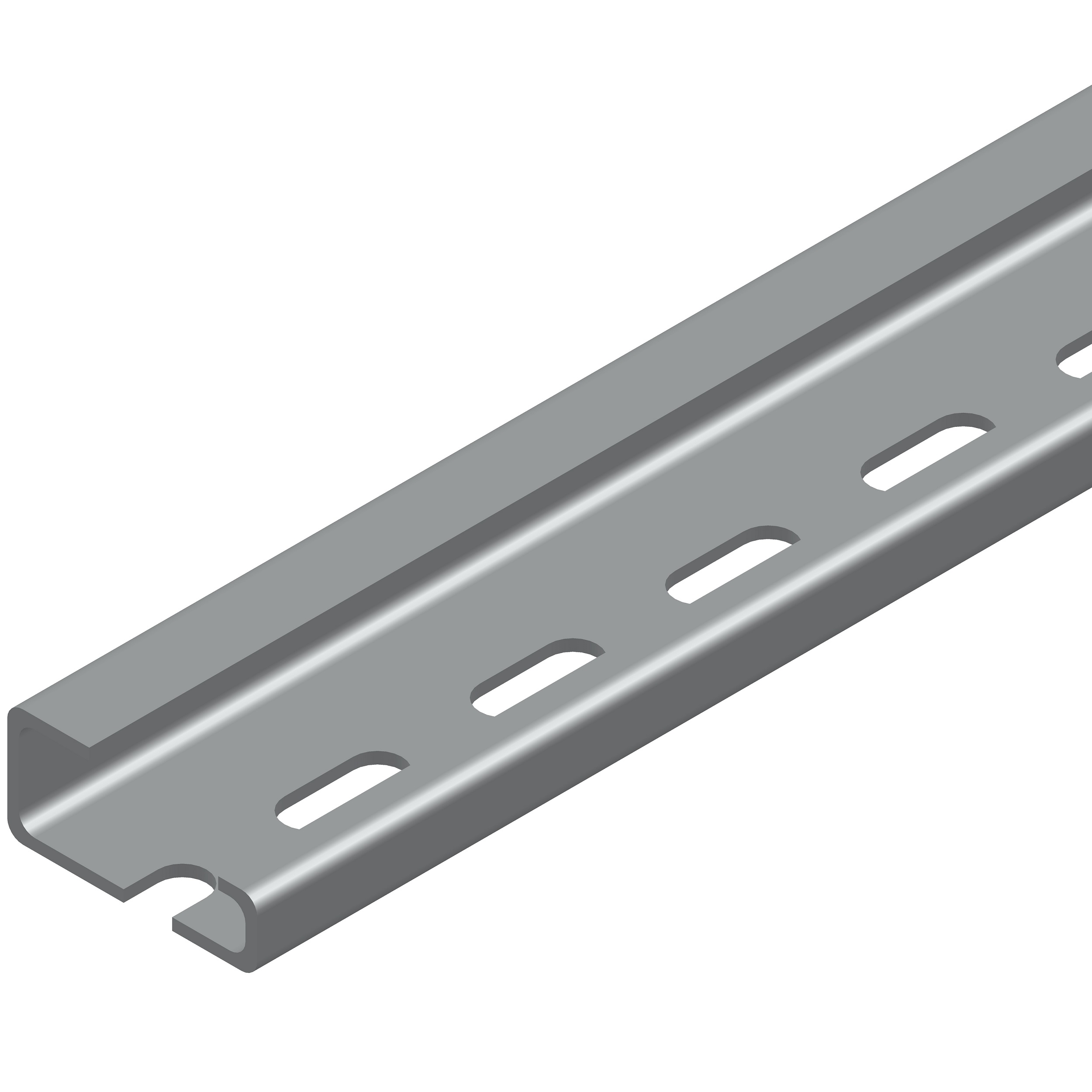
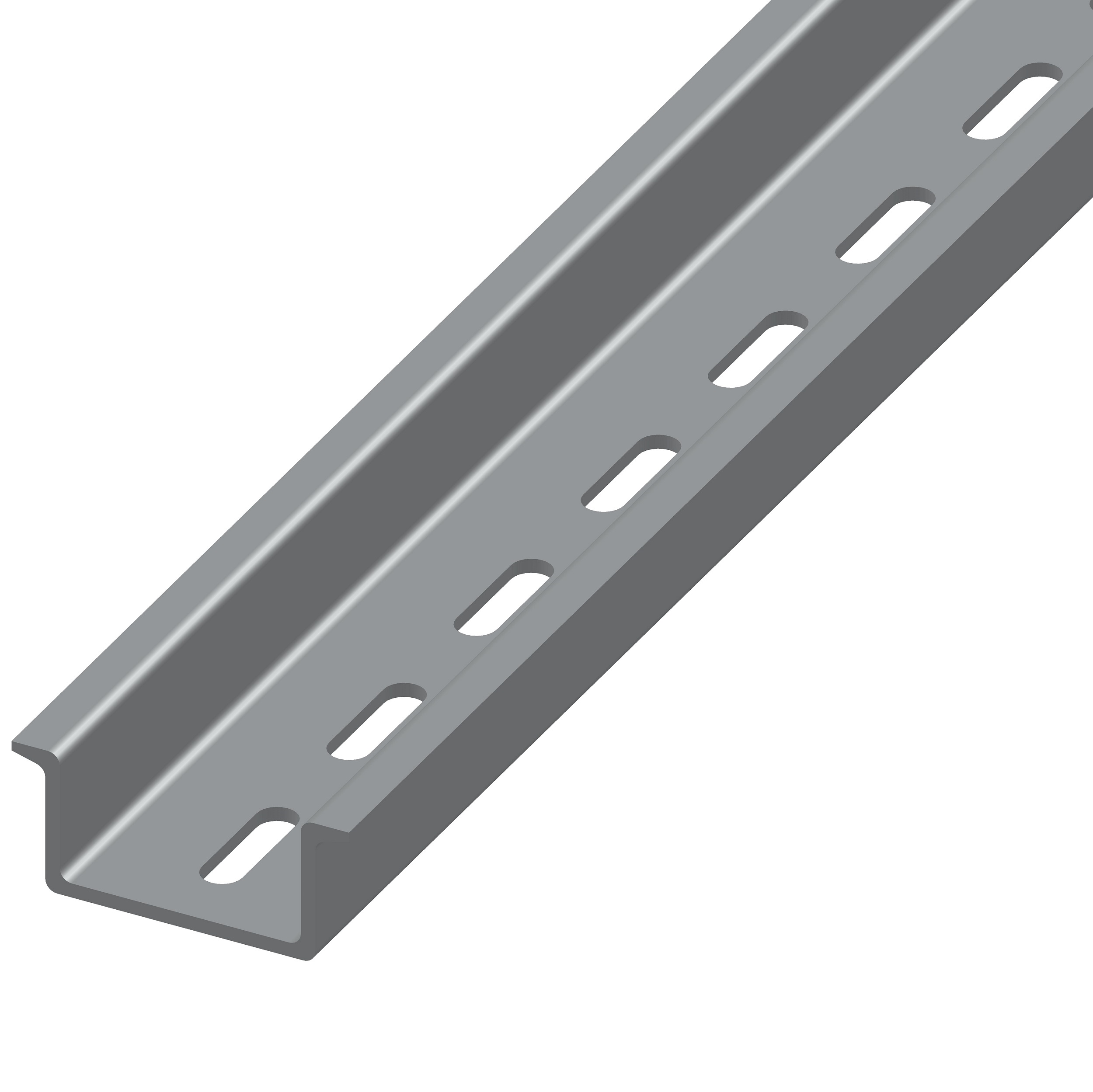
The DIN rail mounting of the SCMPB04 can mount to DIN rail types EN 50022-35x7.5, EN 50022-35x15, EN 50035-G32. These can be purchased as part numbers SCMXRAIL1-XX, SCMXRAIL2-XX, pr SCMXRAIL3-XX where XX is specified as the length of the rail in meters.
Where can I find the MTBF of my module?
Information on MTBF for SCM5B, SCM7B, 8B and DSCA is available on our website. Please see application note AN802 for more details. Application notes can be found under the "Literature" tab on the top navigation bar.
If I input a 5kHz sinusoidal signal into an SCM5B40/41 module, will the output be a 5kHz sinusoidal signal as well?
Yes, signal frequencies lower than the bandwidth of the input module (10kHz for standard products) will pass through to the output. The amplitude of the voltage signal will gained/attenuated based on the I/O specifications of the module.
Is the SCM5B40-06 sensitive to being soldered into a board? Would soldering it damage the part?
We do not recommend soldering the SCM5B pins to a board as it could potentially damage the module. Soldering the pins would also void the warranty.
Many sockets are available which accept the mounting pins. TE Connectivity / AMP part number 50865-5 is an example of these sockets and any equivalent part will work as well.
On the SCM5B modules, what is the purpose of pin 18 (Vin), why is it tied to pin 20 (Vout)? Doesn't Vout provide the output by itself?
Vout is used with input modules, which are all the SCM5B models except for the SCM5B39 and SCM5B49. Vin is used for output modules, SCM5B39 and SCM5B49.
The reason for doing this is because input modules acquire a signal from the field side, and then output a corresponding signal to the system side. On the contrary, output modules acquire a signal from the system side, and then output a corresponding signal to the field side. Since SCM5B backplanes are designed for all channels to accommodate either an input or an output module, the terminal/pin that you would normally get your output signal from if you were using an input module is the same terminal/pin that you would be feeding your input signal to if you were using an output module.
Is the calibration of Dataforth modules traceable to NIST standards?
Yes, calibration of Dataforth modules is traceable to NIST standards.
For the SCM5B40/41-xx, why is the accuracy listed in the datasheet for +/-0.03% but the test datasheet for the module shows +/-0.08%?
The product datasheet lists the typical specs of +/-0.03% for the entire SCM5B41 family (at Ta = 25C and +5VDC power). The +/-0.08% is the maximum limit set during the production test.
Can I use the SCMXBEFE and SCMXSE accessories to make my SCMPB01/2 DIN rail mountable?
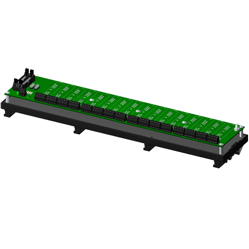
No, converting any of the 16 channel SCM5B backplanes to something DIN rail mountable is a much more involved process than the SCMPB03/04. If you would like a 16 channel SCM5B backplane that can mount on a DIN rail you must purchase an SCMPB01-2, SCMPB01-3, SCMPB02-2 or SCMPB02-3.
Do SCM5B modules with outputs scaled up to 10V have separate power requirements from their 5V counterparts?
No, all SCM5B modules have the same power requirements (5VDC) regardless of their I/O specifications. The power supply current draw of different products in the SCM5B line may vary.
If I purchase a backplane with no CJC, will I still be able to use modules that require the CJC enable jumper to be installed?
Yes. Backplanes with no CJC will still come with the CJC enable installed on the backplane.
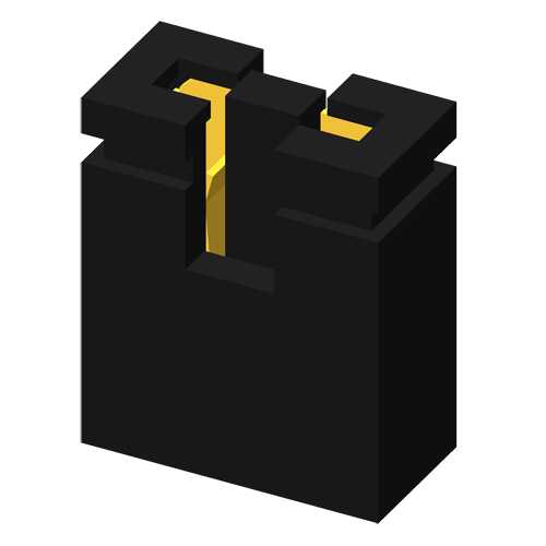
What is the required resistance for jumpers J1 through J4 on my SCM5B backpanel?
J1-J4 on the SCM5B backpanels are jumper cables, so they should have 0 ohm resistance.
Should I ground my sensor wire shield to the 10-32 ground post on the SCMPB01?
It is not recommended to ground the sensor wire shield to the 10-32 ground post on the SCMPB01 because that is the system side ground, while the sensor wire is on the field side. The sensor wire shield should be grounded to the field side ground, which varies based on the signal conditioner you are using. Please see the "Shield Grounding" application note for more information.
Can I use an SCM5B41-07 in my SCMVAS system?
Technically, yes you could use an SCM5B41-07 in your SCMVAS system. However, it is not recommended since the output of all SCMVAS modules are -1 V to 1 V. Since the SCM5B41-07 has a -20 V to 20 V input range, most of that range will go unused while your accuracy suffers as a result since the SCM5B line has +/-0.03% span accuracy.
I just received an SCMPB01 back panel. How should I configure jumpers J1 through J4 for my application?
The factory configuration for jumpers J1 through J4 is the optimal configuration for most applications. If for some reason this jumper configuration will not work/is not working in your application, see our application note AN502 "Ground Connections and Host System Interfaces" for other valid jumper configurations and what situations you would use them.
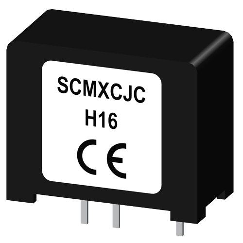
Do I need to purchase the SCMXCJC with my SCMPB03?
No, the SCMPB03 comes with the CJC built into the backpanel.
Do you have an MTBF figure for the SCM5B39? What are the main failure modes?
The failure rate calculations for our SCM5B modules can be found in our application note AN503: https://www.dataforth.com/catalog/pdf/an503.pdf
There are no dominant failure modes.
Can I use an SCM5B module with my OM5-BP-SKT-C?
Yes, any of our SCM5B modules are able to be mounted and operated on Omega's OM5-BP-SKT-C board.
Do you have any SCM5B modules with a 50kHz bandwidth?
None of our standard SCM5B modules have a 50kHz bandwidth. However, it is possible to order a custom SCM5B module with 50kHz bandwidth. Keep in mind that new customs require a 10 pc minimum order and are subject to extra design fees.
Will the isolation on the SCM5B modules support a discharge of 1500VDC without damaging anything connected to the output?
Yes, the SCM5B modules are isolated up to 1500 Vrms, which means that if the common mode voltage between the field side and system side is limited to 1500Vrms, the device will be protected.
However, the input protection for SCM5B modules (i.e., the voltage across the +IN and -IN input terminals) is 240Vrms max.
How does the load resistance of a module affect the noise at the output?
Noise at the output of a module is independent of load resistance.
How do I convert an RMS voltage to its corresponding peak voltage?
To convert an RMS voltage to its corresponding peak voltage, you simply take the RMS voltage value and multiply it by the square root of 2, or roughly 1.414.
For example, 1500Vrms corresponds to a peak voltage of 1500 * 1.414 = 2121 Vp
If the input range of my signal conditioner is -1V to +1V and the output range is 0 to 10V, does this mean that it ignores polarity?
A signal conditioner with these I/O ranges does not mean that the module ignores the polarity of your voltage input. The output of voltage input modules are scaled linearly, meaning an input of -1V would correspond to an output of 0V, an input of 0V would correspond to an output of 5V, an input of +1V would correspond to an output of 10V, and so on.
What is the recommended power supply for Dataforth SCM5B and 8B modules?
The recommended power supply for the Dataforth SCM5B and 8B modules are the linear power supplies in our SCMXPRT/SCMXPRE series. The SCMXPRT/SCMXPRE power supplies output 5V and have options for 1A output current (SCMXPRT-001) or 3A output current (SCMXPRT-003).
The SCMXPRE series is identical to its SCMXPRT counterpart, but is configured for European voltage standards.
The SCMXPRT-001/SCMXPRE-001 both have the option for DIN rail mounting as well (SCMXPRT-001D/SCMXPRE-001D).
Other power supplies that meet that power requirements of the SCM5B and 8B modules can be used as well, but it is strongly recommended to use a linear power supply rather than a switch-mode power supply. Switching power supplies can add noise artifacts to the output of your modules.
Is the SCMXPRT-003 DIN rail mountable?
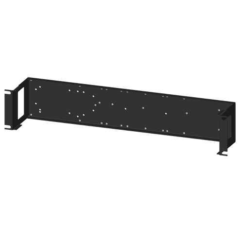
The SCMXPRT-001 has an option for DIN rail mounting (part number: SCMXPRT-001D) but the SCMXPRT-003 does not. Instead, it can be mounted on the SCMXRK-002 which is a 19 inch metal rack for mounting the SCMXPRT-003 as well as various Dataforth backpanels and the SCMXIF interface board.
Analog Devices announced a last time buy and discontinuance of their signal conditioning modules. Can I replace them with Dataforth signal conditioning modules?
Yes, in general, Dataforth signal conditioning modules are a direct replacement for all Analog Devices signal conditioning modules. e.g. "SCM5B35-xx: Linearized 4-Wire RTD Input Modules" will replace Analog Devices "5B35: Isolated 4 Wire RTD Input Signal Conditioning Module".
Please note that Dataforth signal conditioning modules are RoHS II compliant.
Can Dataforth provide calibration reports for modules I purchased?
Yes we can provide calibration reports for the modules that you purchased.
You can either
a) visit https://www.dataforth.com/TestDataReport.aspx to search for Test Report Datasheets by Serial Number or
b) you can send us a list of model numbers and their serial numbers to support@dataforth.com
Can the SCM5B41-09 withstand 300V input without damage?”
The SCM5B41-09 module can withstand 300VDC continuous on its input terminals without damage. However, the output voltage will go to one of the internal power supply rails and remain there for several seconds after the input returns within the specified +/-40V input range
What are feasible failure modes of the SCM5B36 and SCM5B41 devices?
The failures of the Voltage Regulator, Transformers, Oscillator, Analog Switch and the Power Supply Capacitors would cause the module output to go to 0V and the supply current will be 0mA. This failure mode may be accompanied by module supply current many times higher than published specification. These are the common failure modes. Other failure mode may result in output pegging to the output supply rail at 7.5V.
The Inputs are passive nodes and the input failures can cause the module output to go to 0V for both SCM5B41 and SCM5B36 series. The input failures of SCM5B36 may also peg the output to the negative supply rail of -7.5V.
The MTBF (Mean Time Before Failure) for SCM5B36 series is 675,000 hours and the same for SCM5B41 series is 680,000 hours. This failure rate calculation is derived from the MIL-HDBK-217 (Reliability Prediction of Electronic Equipment). The "Part Stress Analysis" method is used at a ground benign environment, +30°C temperature, and quality level B-2 to D-1 depending on the component. The specified humidity level is 95% RH noncondensing.
Keywords/Phrases: SCM5B failure modes, SCM5B36 failure modes, SCM5B41 failure modes
How do the SCM5B49 and SCM5B41 differ?
The major difference is the SCM5B41 is an input module and the SCM5B49 is an output module.
This means that.
The 5B41 module has its input on the isolated field side of the module connect to it through screw terminal blocks. The 5B41 module has its output on the system and power supply side of the module connect to it through ribbon cable connector (SCMPB01, SCMPB02, SCMPB05, and SCMPB06) or screw terminal blocks (SCMPB03, SCMPB04, and SCMPB07).
The 5B49 module has its output on the isolated field side of the module connect to it through screw terminal blocks.
The 5B49 module has its input on the system and power supply side of the module connect to it through ribbon cable connector (SCMPB01, SCMPB02, SCMPB05, and SCMPB06) or screw terminal blocks (SCMPB03, SCMPB04, and SCMPB07).
Keywords/Phrases: 5B, 5B module, 5B input module, 5B output module, 5B41, 5B49.
