


an126: Tuning Surge Tank Level Control Loops
Application Note
Preamble
A surge tank is placed between two processing units (Figure 1) to absorb flow rate fluctuations coming from the upstream process so that the flow rate to the downstream process changes less rapidly. To do this, the tank level has to go up and down. Consequently, the level controller should not try to hold the level as close as possible to its set point. The controller should simply keep the surge tank’s level between its upper and lower limits, and do this with the least possible amount of change to its output.Although there are other methods of controlling the surge tank level, the level-averaging method is preferred by most operators and engineers. This method minimizes control valve movement during disturbances, keeps the level between its limits, and brings the level back to set point in the long term. This Application Note describes how to tune surge tank level controls using the levelaveraging method.
Applicable Process Types
The tuning method described below is intended for use with surge tank levels (Figure 1).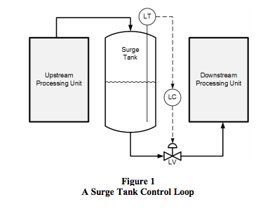
Target Controller Algorithm
The tuning rule presented here is designed for use on a noninteractive controller algorithm with its integral time set in minutes, such as the one provided in the Dataforth MAQ®20 system.Tuning Procedure
To tune the controller for level-averaging control, the residence time of the surge tank, the greatest expected change in flow rate, and the maximum allowable deviation from set point must be known.Residence Time (tres)
The residence time is the time it will take the tank to drain from 100% level to 0% level if there is no flow into the tank and the outlet valve is 100% open. It can be calculated by dividing the volume of the vessel between 0% and 100% of its level measurement span (V) by the maximum flow rate with the outlet valve wide open (Qmax).tres = V / Qmax
The same unit of measure must be used for volume in V and Qmax.
Qmax must be expressed in volume / minute
Change in Flow Rate (Δfmax)
The greatest expected change in flow rate should be expressed as a percentage of maximum valve capacity. If available, historical trends of the level control valve’s position can be used to find the largest change the controller output has made over a relatively short period of time.Maximum Deviation from Set Point (ΔLmax)
The maximum allowable deviation of level from its set point should be specified as a percentage of the full span of the level measurement.Tuning Equations
Once the three quantities described above are available, tuning settings can be calculated for the controller.
KC = 0.74 Δfmax / ΔLmax
TI = 4 tres / KC
TD = 0
TI = 4 tres / KC
TD = 0
Where:
KC is controller gain
TI is the integral time in minutes
TD is the derivative time
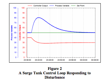
The typical response of a surge tank tuned with the levelaveraging
tuning rule is shown in Figure 2.
TI is the integral time in minutes
TD is the derivative time
Conclusion
While the Ziegler-Nichols and most other tuning methods for level controllers are not suitable for use on surge tanks, using the level-averaging tuning rule will keep the surge tank’s level between its upper and lower limits with the least possible amount of change to the controller’s output.References
The reader is encouraged to visit Dataforth’s website to learn more about PID control and the MAQ®20.- Application Note 122: Introduction to PID Control http://www.dataforth.com/catalog/pdf/AN122.pdf
- MAQ®20 Brochure http://www.dataforth.com/catalog/pdf/MAQ20_broch ure.pdf
Was this content helpful?
Thank you for your feedback!