8B33

Isolated True RMS Input Modules

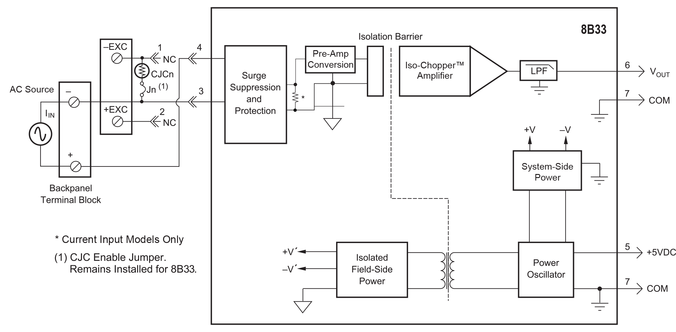
Each 8B33 True RMS input module provides a single channel of AC input which is converted to its True RMS DC value, filtered, isolated, amplified, and converted to a standard process voltage output (see Block Diagram).

The field voltage or current input signal is processed through a pre-amplifier and RMS converter on the field side of the isolation barrier. The converted DC signal is then chopped by a proprietary chopper circuit and transferred across the transformer isolation barrier, suppressing transmission of common mode spikes and surges. The computer side circuitry reconstructs, filters, and converts the signal to an industry standard output of 0 to 5VDC.

Special input circuits provide protection against accidental connection of power line voltages up to 350VAC and against transient events defined by ANSI/IEEE C37.90.1.

Read our Application Note 101, Measuring RMS Values of Voltage and Current.
Certifications

Documents

3D CAD/STEP Files 3D CAD Models
Product Availability
Usually stock to 2-3 weeks

Dimensions & Accessories

Features

  • Interfaces to RMS Voltage (0-300V) or RMS Current (0-1A)
  • Designed for Standard Operation with Frequencies of 45Hz to 1000Hz (Extended Range to 10kHz)
  • Compatible with Standard Current and Potential Transformers
  • Industry Standard Output of 0 to 5VDC
  • ±0.25% Factory Calibrated Accuracy
  • 1500Vrms Transformer Isolation
  • Input Overload Protected to 350Vrms Max (Peak AC & DC) or 2Arms Continuous
  • 120dB CMR
  • 70dB NMR at 60Hz
  • ANSI/IEEE C37.90.1 Transient Protection
  • CE Compliant
  • C-UL-US Listed
  • ATEX Compliance Pending
  • Mix and Match Module Types on Backpanel

Block Diagram

8B33 block diagram
Ordering

FAQ

Is there an alternative for DC coupled input signal conditioning for signal conditioning to RMS? I understand SCM5B33-03 is AC coupled therefore it discards the offset or bias in the DC equivalent computation of the RMS whole signal.
Dataforth does not currently offer an equivalent True RMS module for DC coupled inputs, but a two module solution could be implemented depending on the parameters of the DC offset and the AC waveform. Such an implementation was tested with an SCM5B33-03D True RMS Input Module (0-10Vrms input and 0-10VDC output) and an SCM5B31-02 Narrow Bandwidth Voltage Input Module (+/-5V input and +/-5V output). The inputs to these modules were tied in parallel and connected to a waveform generator with a specified VDC offset and VAC waveform within the input limits of the two modules. The outputs of the modules were then connected in series to get a combined output equal to the sum of their individual output voltages. Both modules were mounted on their own SCMPB03 single channel backplanes in order to maintain separate I/O COM lines for the required series connections to be made on the outputs. Alternatively a single SCMPB07 8-channel backplane could have been used since it allows for isolation of each channel's I/O COM line via a provided jumper. Please note that this combined module configuration will result in a small increase in total error since each module's parameters for accuracy are added up. If a two module configuration is not possible for a specific application, a custom version of the SCM5B33 with revised coupling circuitry might be possible depending on the required specifications. Be aware that custom module designs are subject to NRE charges and require a 10pc minimum quantity order.
Can Dataforth analog modules be used in high vibration environments? If so, what type of testing or certification was completed?
SCM5B, SCM7B, 8B SensorLex, and DSCA modules are well suited for use in high vibration environments. These modules and their associated accessories have undergone testing for random vibration, shock, and swept sine wave vibration. Details of each of these testing methods are provided below: Random Vibration (Operating): ○ MIL-STD 202G, Method 214A, Condition 1 - Frequency Range: 50-2000Hz, flat spectrum - Vibration Intensity: 7.56 Grms - Duration: 10min/axis (X, Y, Z) Shock (Operating): ○ MIL-STD-810F, Method 516.5 - Pulse Shape: Sawtooth - Test Level: 30G - Duration 11ms - Orientation: +/-X, +/-Y, +/-Z Swept Sine Vibration (Operating) ○ MIL-STD-810G, Method 514.6, modified - Frequency Range: 10-2000Hz - Vibration Intensity: 5Gp-p - Sweep Rate: 1 octave/min - Orientation: X, Y, Z Declaration of conformity for the above-listed tests can be provided upon customer request. Please contact customer service if a copy of the declaration is needed.
Due to resource constraints on my computer, I'm unable to open the three dimensional CAD models provided on your website. Does Dataforth provide two demensional CAD models for download as well?
Two dimensional CAD models can be generated upon customer request. Please contact Customer Service for assistance.
What does it mean when an input module has for example a 3kHz bandwidth?
A 3kHz bandwidth on an input module means it can accept voltages from DC to 3000Hz. Any frequency higher than that and the signal will start to be attenuated by the filter at the input.
Does the 8B series backplanes identify the module slots on the PWB via silkscreen or other methods? Does it also mark the terminal blocks +/- inputs?
The 8B backpanels identify the module slots and their associated terminal block with silkscreen text (this includes the +/- inputs). The text is descriptive and matches up with the diagrams in our datasheets.
Can SCM5B modules be hot swapped?
Not just SCM5B modules, but any signal conditioning module series and MAQ20 I/O modules can be hot swapped. A minimal amount of signal settling time may result, but there will be no damage to the device.
What does "Response time, 90% span" mean on the datasheet for my module?
Normally, a response time figure refers to how quickly a module's output can "respond" to a change in the input signal. "Response time, 90% span" refers to how fast a module can adjust its output when a step signal is applied at the input, where the magnitude of this step input is 90% of the input span of the module.
Where can I find the MTBF of my module?
Information on MTBF for SCM5B, SCM7B, 8B and DSCA is available on our website. Please see application note AN802 for more details. Application notes can be found under the "Literature" tab on the top navigation bar.
Is the calibration of Dataforth modules traceable to NIST standards?
Yes, calibration of Dataforth modules is traceable to NIST standards.
Why do only a few 8B modules have a +/-5V output?
Some 8B modules (such as 8B34 and 8B47) cannot have bipolar output due to limitations in the internal linearization circuitry.
If I purchase a backplane with no CJC, will I still be able to use modules that require the CJC enable jumper to be installed?
Yes. Backplanes with no CJC will still come with the CJC enable installed on the backplane.
If I don’t have an 8BPWR-2, can I use a +5VDC power supply to power my 8B backplane?
Yes, you can. The 8BPWR-2 is not required to power the 8B backplanes, it is used in situations where you don't have a +5VDC power supply and need to regulate the voltage of whatever current power supply you are using down to +5VDC so that it can be used for the 8B backplane. Please make sure when choosing your +5VDC power supply that the current rating of the supply is acceptable for the total current draw of your system.
Can I power multiple 8B backplanes off of a single power supply?
You can use a single 5V power supply to power multiple backplanes, but you need to be aware of the current rating of your power supply and the current draw of your 8B modules. The current rating of your power supply needs to be greater than the total current draw of all the modules in your system (ideally 1.5x the total current draw). You can check the current draw of various 8B modules by checking their datasheets.
What is the correct backpanel for my 8B38 module?
Any of the backpanels in the 8B series will work for the 8B38 module. In fact, any of the 8B modules can be mounted to any of the 8B backpanels.
How does the load resistance of a module affect the noise at the output?
Noise at the output of a module is independent of load resistance.
How do I convert an RMS voltage to its corresponding peak voltage?
To convert an RMS voltage to its corresponding peak voltage, you simply take the RMS voltage value and multiply it by the square root of 2, or roughly 1.414. For example, 1500Vrms corresponds to a peak voltage of 1500 * 1.414 = 2121 Vp
If the input range of my signal conditioner is -1V to +1V and the output range is 0 to 10V, does this mean that it ignores polarity?
A signal conditioner with these I/O ranges does not mean that the module ignores the polarity of your voltage input. The output of voltage input modules are scaled linearly, meaning an input of -1V would correspond to an output of 0V, an input of 0V would correspond to an output of 5V, an input of +1V would correspond to an output of 10V, and so on.
What is the recommended power supply for Dataforth SCM5B and 8B modules?
The recommended power supply for the Dataforth SCM5B and 8B modules are the linear power supplies in our SCMXPRT/SCMXPRE series. The SCMXPRT/SCMXPRE power supplies output 5V and have options for 1A output current (SCMXPRT-001) or 3A output current (SCMXPRT-003). The SCMXPRE series is identical to its SCMXPRT counterpart, but is configured for European voltage standards. The SCMXPRT-001/SCMXPRE-001 both have the option for DIN rail mounting as well (SCMXPRT-001D/SCMXPRE-001D). Other power supplies that meet that power requirements of the SCM5B and 8B modules can be used as well, but it is strongly recommended to use a linear power supply rather than a switch-mode power supply. Switching power supplies can add noise artifacts to the output of your modules.
Is the SCMXPRT-003 DIN rail mountable?
The SCMXPRT-001 has an option for DIN rail mounting (part number: SCMXPRT-001D) but the SCMXPRT-003 does not. Instead, it can be mounted on the SCMXRK-002 which is a 19 inch metal rack for mounting the SCMXPRT-003 as well as various Dataforth backpanels and the SCMXIF interface board.
Analog Devices announced a last time buy and discontinuance of their signal conditioning modules. Can I replace them with Dataforth signal conditioning modules?
Yes, in general, Dataforth signal conditioning modules are a direct replacement for all Analog Devices signal conditioning modules. e.g. "SCM5B35-xx: Linearized 4-Wire RTD Input Modules" will replace Analog Devices "5B35: Isolated 4 Wire RTD Input Signal Conditioning Module". Please note that Dataforth signal conditioning modules are RoHS II compliant.
Can Dataforth provide calibration reports for modules I purchased?
Yes we can provide calibration reports for the modules that you purchased. You can either a) visit https://www.dataforth.com/TestDataReport.aspx to search for Test Report Datasheets by Serial Number or b) you can send us a list of model numbers and their serial numbers to support@dataforth.com
I have an 8B33 module, what is the accuracy error between 0-5% span?
In the 8B33 data sheet, Note 4, For 0-5% Span measurements add 1% accuracy error (-02, -03, -04, -05) or 1.5% accuracy error (-01, -06). Accuracy error includes linearity, hysteresis and repeatability but not source or external shunt inaccuracy (if used).

Keywords/Phrases: 8B RMS, 8B True RMS, 8B RMS input module, 8B True RMS input module, 8B33 accuracy, span, offset
Can you explain what is the difference between the “Standard frequency range” and the “Extended frequency range” for the 8B33 module? I don’t see an option to order different module type so how are the two frequency ranges accessible to the user ?
The user does not have to do anything special; the module operates seamlessly over the full frequency range of 45Hz to 10kHz. We needed to split the full frequency range into two ranges so we could define and specify the different accuracy levels associated with each subrange.
If you look further down the 8B33 Specifications under Accuracy, you will notice the extended frequency range carries an additional +/-1.375% Span error and +/-3.25% Span error (-06). This error is in addition to the +/-0.25% Span error at 50/60Hz. So the total accuracy error will be +/-0.25% + (+/-1.375%) = +/-1.625% Span and . +/-0.25% + (+/-3.25%) = +/-3.50% Span.

Keywords/Phrases: 8B RMS, 8B True RMS, 8B RMS input module, 8B True RMS input module, 8B33

Custom Modules

Below is a list of existing custom modules. If you don't see a module matching your target specifications, contact Customer Service and Application Support to discuss design guidelines and design feasibility. Customer Service and Application Support can be reached at sales@dataforth.com or +1-800-444-7644.
* ... Status Codes: PR = Production, PT = Prototypes, QU = Quoted

We want your feedback!

We are interested in your feedback regarding our products. Please let us know what you think and if you have any questions regarding the SCM5B32 and how this product could apply to your application. Your feedback is very valuable to us and very much appreciated.

Was this content helpful?
Thank you for your feedback!
Menu
Top