


an110: 3-Phase AC Calculations Revisited
Application Note
Preamble
This application note is a continuation of Dataforth’s Application Note AN109, which contains AC system definitions and basic rules for calculations with examples. The reader is encouraged to review AN109, References 3, 4, and 5 as background for this Application Note.The Three-Phase Voltage System
Three-phase voltage systems are composed of three sinusoidal voltages of equal magnitude, equal frequency and separated by 120 degrees.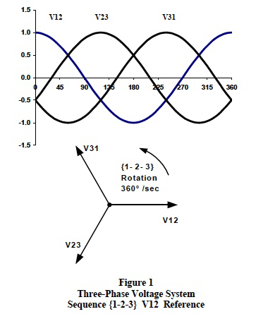
Figure 1 illustrates real-time cosine functionality and associated phasor notation for a 3-phase line-to-line voltage system with line voltage V12 as reference.
Review of Three-Phase Voltage System Properties
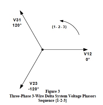
Three-phase supply voltages and load systems have two basic configurations; the 4-wire “wye” and the 3-wire “delta”. Figure 2 illustrates a basic 3-phase 4-wire wye configured voltage system with V1N as reference and Figure 3 shows a 3-wire delta configured voltage system with V12 as reference respectively.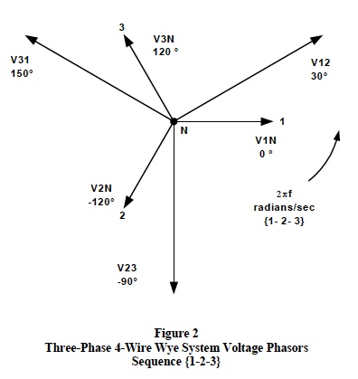
Important definitions, conventions, and calculation rules for both the 3-phase 4-wire wye and the 3-wire delta configured voltage systems are itemized in the following list with the “messy” vector math omitted.
Phasor Orientation:
By definition, all sinusoidal phasors rotate in the counterclockwise direction with a {1-2-3} or {3-2-1} sequence and angles are measured as positive in the counterclockwise direction. A 4-wire 3-phase wye system is shown in Figure 2 with V1N chosen as reference. The line-to-line voltages are V12, V23, and V32 with the lineto- neutral voltages shown as V1N, V2N, and V3N. Figure 3 shows the proper line-to-line phasor voltages for a 3- phase 3-wire delta configuration with V12 phasor chosen as reference. Note: Any phasor can be chosen as reference, the choice is completely arbitrary.
Phase Sequence:
A phase sequence defines the sequential timing by which each line voltage phasor lags each other line voltage phasor in the counterclockwise direction. Figures 1, 2 and 3 show a {1-2-3} phase sequence. A {1-2-3} sequence means that V12 leads V23 by 120 degrees and V23 leads V31 by 120 degrees. In addition, V1N leads V2N by 120 degrees and V2N leads V3N by 120 degrees. It is necessary to establish the phase sequence before making any calculations in order that calculated vector phasor angles can becorrectly located relative to each other.
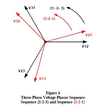
There are only two valid phase sequences; the {1-2-3} sequence and the {3-2-1} sequence. Both these phase sequences are determined by how the 3-phase transformer supply lines (L1, L2, L3) are connected and labeled. Figure 4 illustrates the {3-2-1} sequence relative to the {1-2-3} sequence. Note: The phase sequence can be changed by simply reversing the connections of any two of the three (L1, L2, L3) supply lines; however, this should only be done in accordance with all the proper codes, regulations, and approval of the plant engineering staff.
Subscripts:
Maintaining the proper subscript order for all phasor quantities is one of the most important keys to successful 3-phase calculations. Figure 4 shows the proper subscript order for each of the two different phase sequences. For sequence {1-2-3}, the proper order of subscripts is [12], [23], and [31]; whereas, the proper subscript order for sequence {3-2-1} is [32], [21], and [13].
Subscript Notation:
Once the phase sequence is determined and the proper subscripts are identified, calculations using these subscripts together with the conventions adopted for the AC version of Ohm’s Law will prevent angle errors.
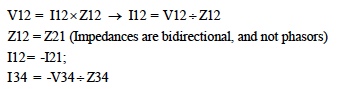
By convention, V12 is the phasor voltage drop plus (1) to minus (2) in the direction of current flowing from point (1) toward point (2) and is equal to this current multiplied by the AC impedance between points (1) and (2). For example in phasor notation;
Phasor Addition/Subtraction:
Proper subscript notation establishes the correct method for vector addition/subtraction of phasors. In Figure 2 the line-to-line voltage phasors in this 3-phase {1-2-3} sequence 4-wire wye system are composed of line-toneutral phasor voltages as follows;
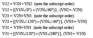
If the RMS line-to-neutral voltages are all equal (standard balanced system), then the above equations show that all line-to-line phasor supply voltages are line-to-neutral voltages multiplied by 3 and lead the line-to-neutral voltage phasors by 30 degrees. For example, a standard 4-wire 3-phase wye system with line-to-neutral voltages of 120 volts and V1N chosen as the reference phasor at zero degrees has line-to-line voltages of;
V12 = 208∠ 30°; V23 = 208∠ -90°; V31 = 208∠ 150° .
Important concept: A 3-phase 3-wire delta configured system of balanced voltages does not actually have lineto- neutral voltages like the wye system. However, the delta line-to-line voltages as shown in Figure 3 can still be constructed from a theoretical set of balanced 3-phase line-to-neutral voltages as illustrated above. The relationships with these theoretical voltages are extremely useful in locating delta phasor angles.
Calculation Procedures, Guidelines, and Formulae
The following list of procedures, guidelines and formulae illustrate an outline of how to calculate 3-phase phasor quantities using typical nameplate data taken from individual load units.Calculations proceed as follows;
- Identity the phase sequence; {1-2-3} or {3-2-1}
- Identify subscripts; [12], [23], [31] or [32], [21], [13]
- Assume L1, L2, L3 line currents flow toward loads and neutral (return) current flows toward supply.
- Load current flows and voltage drops must follow the subscript notations as previously defined.
- Use “Ohm’s Law for AC” to calculate magnitudes and angles of each individual single-phase load current. Review Dataforth’s AN109, Reference 1.
- Important concepts: Line currents for both wye and
delta balanced 3-phase loads are calculated using the
following relationships;
- AC input power = 3 x (Vline) x (Iline) x PF
- PF is the cosine of the angle by which line currents lead or lag the line-to-neutral voltage. Three-phase line-to-neutral voltages actually exist in wye configurations; whereas, they are theoretical in delta configurations. For example, assume any balance 3-phase load with 10 amps of line current and a PF of 0.866 (30° ) lagging. If system sequence is {1-2-3} and V12 is reference, then I1=10∠ -60°; I2=10∠ 180°; I3=10∠ 60° .
- Determine the power triangle quantities; watts “P” and VARs “Q” for each load. Review Reference 1.
- Sum the previously calculated individual load currents using proper subscript notation to determine each individual line current
- Finally, sum all the individual load power triangle quantities (Watts “P” and VARs “Q”) to establish the system power triangle quantities; P, Q, and PF. It this final step that establishes how a system’s load population behaves.
Calculation Examples
The following examples assume a typical 208-120 volt three-phase 4- wye configuration with a phase sequence of {1 2 3}, and V12 chosen as reference. This is a wye system; however, loads connected between each of the three individual supply lines (L1, L2, L3) constitute a 208-volt 3-wire delta configuration. Three categories of single-phase loads are assumed for the following calculations. These categories are identical to those defined in Application Note AN109 (Reference 1) and listed below with the required nameplate data.- Output Kilowatts; KW, Efficiency (optional), PF= 1
- Output Horsepower; HP, Efficiency, P
- Input KVA; KVA, PF, Efficiency is 100%.
Table 1 shows calculated values for an assumed population of these loads. Readers should verify these calculations. Dataforth offers an interactive Excel workbook similar to Table 1, which automatically calculates all the 3-phase system quantities. See Reference 2 to download down load this Excel file.
Example Calculations for Line-to-Neutral Loads
Three-phase wye systems with neutrals can have equal or unequal individual single-phase loads connected between any of the supply lines (L1, L2, L3) and neutral. Systems are balanced if all line-to-neutral loads are identical.
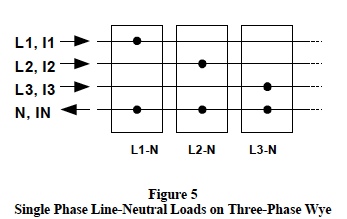
Figure 5 shows three groups of single-phase line-toneutral loads connected on a three-phase wye system. This configuration of single-phase loads can be considered as a composite unbalanced wye load
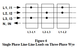
Figure 6 shows three groups of single-phase line-to-line loads connected on a three-phase wye system. This configuration of single-phase loads can be considered as a composite unbalanced delta load
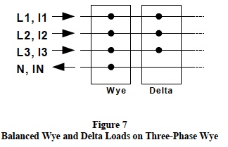
Figure7 shows a group of balanced wye loads and a group of balanced delta loads both of which are (can be) connected on a three-phase wye system.
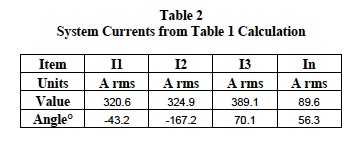
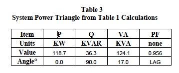
Table 1 is a composite set of calculated results for the configurations shown in Figures 5, 6, and 7. These calculations assume an arbitrary population of the type loads previously defined and employ all the rules, procedures, and definitions as illustrated above. The system results from Table 1 calculations are shown below in Tables 2 and 3.
Line voltage V12 (208 at zero degrees) is reference for the above current angles.
Readers are encouraged to verify these calculations.
As mentioned above, Dataforth provides an interactive Excel file designed to assist the enthusiastic investigator in calculating system currents and associated power levels. This file allows an investigator to enter nameplate data for all the system loads; whereupon, all line current phasors and power quantities are automatically calculated. Dataforth’s “Excel Interactive Work Book for Three- Phase AC Calculations” can be downloaded from Dataforth’s web site, see Reference 2 .
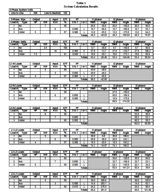
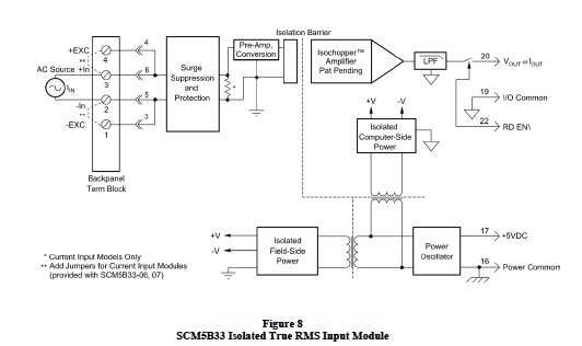
Figure 8 is an illustration of Dataforth’s Isolated True RMS Input Module, SCM5B33. This function is also available in a DIN rail package; the DSCA33. Dataforth has a collection of signal conditioning modules designed specifically for measuring AC RMS high-voltage parameters using built-in attenuation. The reader is encouraged to visit References 1, 6, 7, and 8. Dataforth References The reader is encouraged to visit Dataforth’s web site and explore their complete line of isolated signal conditioning modules and related application notes, see references shown below.
- Dataforth Corp., http://www.dataforth.com
- Dataforth Corp., AN110 Excel Interactive Work Book for Three Phase AC Calculations
- Dataforth Corp., Application Note AN109, Single Phase AC Measurements
- Dataforth Corp., AN109 Excel Interactive Work Book for Single Phase AC Calculations
- National Electric Code controlled by National Fire Protection Agency, NFPA
- Dataforth Corp., SCMVAS Voltage Attenuator System,
- Dataforth Corp., SCM5B33 Series of Modular True RMS Signal Conditioners
- Dataforth Corp., DSCA33 Series of DIN Mount True RMS Signal Conditioners
Was this content helpful?
Thank you for your feedback!