


an111: Current Modules Measure Power Factor
Application Note
Preamble
The "power factor" of AC systems or components is the cosine of the angle by which the AC current leads or lags the applied AC excitation voltage. The physics of inductance and capacitance behavior establishes the voltage-current relationship, which depends on both the AC excitation’s amplitude and time rate of change (i.e. derivative wrt time). This behavior causes a phase shift phenomena between voltage and current, which increases line losses, thereby increasing the supply line current required to produce a given amount of useful output power. Utility companies often charge a penalty for a customer’s unacceptable power factor. It is important for the consumer of electrical energy to be aware of power factor and the available methods for correction. See Ref 2, Dataforth’s Application Note AN109, for a review of single AC circuit behavior.Practical Illustrations
Figure 1 shows a single-phase inductive load with a supply voltage wiring resistance, which is responsible for undesirable line losses and lowered load voltage, VL.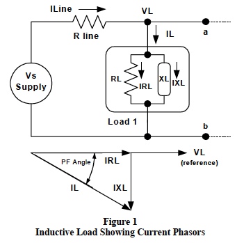
The current phasors shown in Figure 1 illustrate that an inductive reactive load component creates a 90-degree lagging phase shift between the applied load voltage and the input line current. The power dissipated in the resistive component of a given load is responsible for useful work and is RL*IRL2 . Loads containing either inductive or capacitive reactive components (PF < 1), have line currents greater than that (IRL) required for producing the useful output, RL*IRL2 . This means larger line losses, lower load voltages, and higher utility costs.
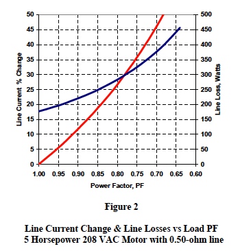
Figure 2 illustrates the effect on line current and associated line losses caused by changing the power factor of a 5 horsepower single-phase 208 VAC motor delivering a constant output power (requires small speed changes). This example assumes a total of 0.50-ohm line resistance, 0.25 ohms in each wire.
Clearly, power factors (PF) can have a costly impact on electrical utility costs.
Any load or section of a facility can be represented by its “power triangle”. Figure 3 shows some typical power triangle examples. The accepted convention plots the total KW resistive power (line losses plus useful output) on the positive x-axis and reactive power (KVAR) on the y-axis. Inductive KVAR is defined as positive and capacitive KVAR as negative. Surprisingly, KVAR does no useful work! Applied voltage multiplied by input line current is the “apparent power”, KVA, and is the vector sum of KW and KVAR.
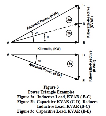
Power Triangles illustrate the following useful relationships;
- Reactive Power (KVAR), which does no useful output work, is the sum of Inductive and Capacitive reactive power and can be tailored by adding external capacitance.
- Line current is equal to the supplied apparent power (KVA) divided by the supply voltage (Vs). Note : Line current is reduced when the reactive power (KVAR) is reduced, which in turn reduces the power factor angle.
Suggestions
In many situations, it is cost effective to analyze system cells, load groups, and individual loads to determine existing power factors and if there is a return on the investment needed to improve them. Utility companies have resources and personnel available to do on-site investigations. Plant personnel can conduct their own electrical system studies with commercially available equipment.Figure 4 illustrates a scheme whereby one can make three AC current measurements with standard off-the-shelf AC current transformers (CTs) and Dataforth’s line of isolated true rms signal conditioning modules to develop a measurement scheme for either on-line real time or individual stand-alone measurements.
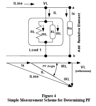
The scheme shown in Figure 4 requires three current measurements; load current, line current, and the current flowing in an external resistor. This external resistive element can simply be a configuration of incandescent bulbs or a resistive heating element selected such that the external current (Ix) is in the neighborhood of 10% of the rated load current. Equation 1 gives a relationship for calculating the power factor (PF) magnitude from RMS measurements of the currents; Iline, IL, and Ix shown in Figure 4.
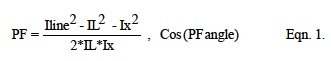
Combinational calculation errors generated by using Eqn.1 are unavoidable. The difference of squared numbers divided by the product of numbers produces a result with tolerance errors larger than those associated with the tolerance error in each individual number. For the example shown in Figure 2, results from 200 random calculations of Eqn. 1 show a ± 5% tolerance in PF using ± 0.25% accuracy in the measured currents. Precise measurements are necessary to minimize combinational calculation errors.
Dataforth Isolated True RMS AC modules are well suited for implementing measurement techniques such as those shown above. Dataforth RMS modules measure RMS values of AC voltages (0 -300 Vrms) directly or RMS values of AC currents (0-5 Arms) using conventional current transformers (CT). These RMS modules have a DC voltage output representing RMS values with a linear scale factor. Note that a RMS to DC scale factor has no effect in Eqn.1, since the scale factor appears in both numerator and denominator.
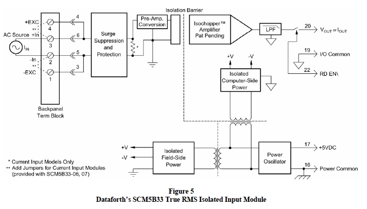
Figure 5 illustrates Dataforth’s SCM5B33 True RMS Isolated Signal Conditioning Module circuit topology, designed for measuring RMS values over a frequency range of 45 Hz up to 20kHz and is available in 5B or Din Rail Modules. See Ref. 1, Dataforth website catalog for complete specifications.
A Word of Caution: When making current measurements with conventional current transformers (CT) never leave the current transformer secondary leads open circuit. Current transformers are usually torrid in shape and the high current (primary) side has only a few turns (generally 1) whereas the secondary has many turns in order to reduce the secondary current down to an industry standard level. For example, a 500-amp current transformer would have a 5-amp output for 500-amp input, a current reduction of 100, but the voltage has a step-up factor of 100. It is possible to have an open circuit current transformer secondary with the primary side connected into a 440 Vac system, resulting in 44000 volts on the open secondary. Properly designed CTs have built in protection; however, it is wise to assume the worst and always take appropriate safety precautions.
Preamble
Dataforth References
- Dataforth Corp., Application Note AN109: Single Phase AC Measurements (Revisited)
Was this content helpful?
Thank you for your feedback!