


SCM9B-1000/2000
Sensor-to-Computer Modules
The SCM9B-1000/2000 Sensor-to-Computer Modules are a family of complete solutions designed for data acquisition systems based on personal computers and other processor-based equipment with standard serial I/O ports. The modules convert analog input signals to engineering units and transmit in ASCII format to any host with standard RS-485 or RS-232C ports. These modules can measure temperature, pressure, voltage, current and various types of digital signals. The modules provide direct connection to a wide variety of sensors and perform all signal conditioning, scaling, linearization and conversion to engineering units. Each module also provides digital I/O lines for controlling devices through solid state relays or TTL signals. These digital I/O lines along with built-in limit setting capability provide alarm and control outputs.
The modules contain no pots or switches to be set. Features such as address, data rate, parity, alarms, echo, etc. are selectable using simple commands over the communications port—without requiring access to the module. The selections are stored in nonvolatile EEPROM which maintains data even after power is removed.
The 2000 series is an enhanced version of the 1000 series of sensor interfaces. The 2000 series allows the user to scale the output data in any desired engineering units. The 2000 also provides the ability to program nonlinear transfer functions. This feature may be used to linearize nonstandard sensors or to provide outputs in engineering units which are nonlinear functions of the input.
Programmable Features (2000 Series)
- Provides intelligent features not found in the 1000 series
- ASCII Output Scaled to Desired Engineering Units
- User Programmable Nonlinear Transfer Function
- Straight-Line Segment Approximation: up to 24 Segments
Certifications

Documents
Product Availability
Usually stock to 3-5 weeks. Contact Customer Service for current lead times.
Dimensions & Accessories
Features
- Complete Sensor to RS-485 or RS-232C Interface
- ASCII Format Command/Response Protocol
- 500Vrms Analog Input Isolation
- 15-Bit Measurement Resolution
- Continuous Self-Calibration; No Adjustments of Any Kind
- Programmable Digital Filter
- Digital Limit Setting and Alarm Capability
- Digital Inputs and Outputs Connect to Solid State Relays
- Events Counter to 10 Million
- Requires +10V to +30VDC Unregulated Supply
- Transient Suppression on RS-485 Communications Lines
- Screw Terminal Plug Connectors Supplied
- CE Compliant
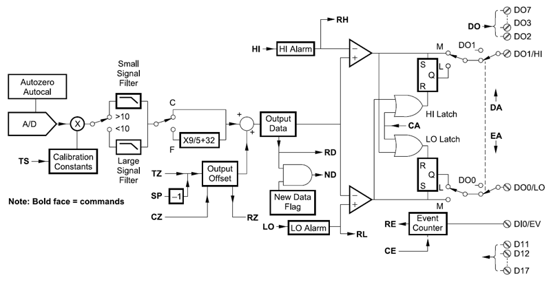
Block Diagram
Ordering
SCM9B-1100-2100 Voltage Inputs
NOTE: Data in below table can be filtered. Please use the
to make your selection. If you have any questions about the displayed data,
please contact Customer Service at +1 520-741-1404 or sales@dataforth.com
SCM9B-1200-2200 Current Inputs
NOTE: Data in below table can be filtered. Please use the
to make your selection. If you have any questions about the displayed data,
please contact Customer Service at +1 520-741-1404 or sales@dataforth.com
SCM9B-1300 Thermocouple Inputs
NOTE: Data in below table can be filtered. Please use the
to make your selection. If you have any questions about the displayed data,
please contact Customer Service at +1 520-741-1404 or sales@dataforth.com
SCM9B-1400 RTD Inputs
NOTE: Data in below table can be filtered. Please use the
to make your selection. If you have any questions about the displayed data,
please contact Customer Service at +1 520-741-1404 or sales@dataforth.com
SCM9B-1400 Thermistor Inputs
NOTE: Data in below table can be filtered. Please use the
to make your selection. If you have any questions about the displayed data,
please contact Customer Service at +1 520-741-1404 or sales@dataforth.com
SCM9B-1500-2500 Strain Gage Inputs
NOTE: Data in below table can be filtered. Please use the
to make your selection. If you have any questions about the displayed data,
please contact Customer Service at +1 520-741-1404 or sales@dataforth.com
SCM9B-1600-2600 Time/Frequency Inputs
NOTE: Data in below table can be filtered. Please use the
to make your selection. If you have any questions about the displayed data,
please contact Customer Service at +1 520-741-1404 or sales@dataforth.com
Accessories
View accessories available for this generic product's orderable products.
Custom Modules
Below is a list of existing custom modules. If you don't see a module matching your target specifications, contact Customer Service and Application Support to discuss design guidelines and
design feasibility. Customer Service and Application Support can be reached at
sales@dataforth.com or +1-800-444-7644.
NOTE: Data in below table can be filtered. Please use the
to make your selection. If you have any questions about the displayed data,
please contact Customer Service at +1 520-741-1404 or sales@dataforth.com
* ... Status Codes: PR = Production, PT = Prototypes, QU = Quoted
FAQ
We want your feedback!
We are interested in your feedback regarding our products. Please let us know what you think and if you have any questions regarding the SCM5B32 and how this product could apply to your application. Your feedback is very valuable to us and very much appreciated.
Was this content helpful?
Thank you for your feedback!