SensorLex® 8B Series: Isolated Analog Signal Conditioners. Dataforth

Isolated Analog Signal Conditioners

8B MODULES

8B Miniature Signal Conditioners

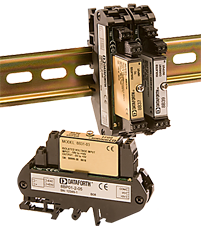
Dataforth's new SensorLex® 8B line of isolated analog signal conditioners provides 19 family groups with a total of 123 models that interface to a wide variety of voltage, current, temperature, position, frequency, and strain measuring devices. Housed in a package only one-fifth the size of competing products, the 8B offers fully functional Instrument Class® performance with superior specifications such as ±0.05% accuracy, ±0.02% linearity, 5-pole filtering, 1500Vrms isolation, low output noise and much more.


APPLICATIONS

Designed for Embedded Applications

  • PC/104 Embedded Solutions
  • Compact PCI Systems
  • VMEbus Systems
  • PXI Systems

Protects User Equipment from Lightning and 

Industrial Equipment Power-Line Voltage

Reduces Electrical Noise in Measured Signals

Convenient System Expansion and Repair


CUSTOM SIGNAL CONDITIONING

Custom modules are available: consult factory for minimum quantity and pricing details on custom input ranges, output ranges, bandwidth, and other key parameters.

Features

  • ±0.05% Accuracy (Typical)
  • ±0.02% Linearity
  • 1500Vrms Transformer Isolation & up to
  • 240Vrms Field-side Protection
  • ANSI/IEEE C37.90.1 Transient Protection
  • 5V Power (30mA Typical)
  • 5-Pole Low-Pass Filtering
  • Up to 120dB CMR
  • 70dB NMR at 60Hz
  • -40°C to +85°C Operating Temperature
  • CE Compliant
  • C-UL-US Listed (Class I, Division 2, Groups A, B, C, D)
  • ATEX Compliance Pending
  • Manufactured per RoHS Directive (EU) 2015/863 (RoHS 3)

FAQ

Is there an alternative for DC coupled input signal conditioning for signal conditioning to RMS? I understand SCM5B33-03 is AC coupled therefore it discards the offset or bias in the DC equivalent computation of the RMS whole signal.
Dataforth does not currently offer an equivalent True RMS module for DC coupled inputs, but a two module solution could be implemented depending on the parameters of the DC offset and the AC waveform. Such an implementation was tested with an SCM5B33-03D True RMS Input Module (0-10Vrms input and 0-10VDC output) and an SCM5B31-02 Narrow Bandwidth Voltage Input Module (+/-5V input and +/-5V output). The inputs to these modules were tied in parallel and connected to a waveform generator with a specified VDC offset and VAC waveform within the input limits of the two modules. The outputs of the modules were then connected in series to get a combined output equal to the sum of their individual output voltages. Both modules were mounted on their own SCMPB03 single channel backplanes in order to maintain separate I/O COM lines for the required series connections to be made on the outputs. Alternatively a single SCMPB07 8-channel backplane could have been used since it allows for isolation of each channel's I/O COM line via a provided jumper. Please note that this combined module configuration will result in a small increase in total error since each module's parameters for accuracy are added up. If a two module configuration is not possible for a specific application, a custom version of the SCM5B33 with revised coupling circuitry might be possible depending on the required specifications. Be aware that custom module designs are subject to NRE charges and require a 10pc minimum quantity order.
Can Dataforth analog modules be used in high vibration environments? If so, what type of testing or certification was completed?
SCM5B, SCM7B, 8B SensorLex, and DSCA modules are well suited for use in high vibration environments. These modules and their associated accessories have undergone testing for random vibration, shock, and swept sine wave vibration. Details of each of these testing methods are provided below: Random Vibration (Operating): ○ MIL-STD 202G, Method 214A, Condition 1 - Frequency Range: 50-2000Hz, flat spectrum - Vibration Intensity: 7.56 Grms - Duration: 10min/axis (X, Y, Z) Shock (Operating): ○ MIL-STD-810F, Method 516.5 - Pulse Shape: Sawtooth - Test Level: 30G - Duration 11ms - Orientation: +/-X, +/-Y, +/-Z Swept Sine Vibration (Operating) ○ MIL-STD-810G, Method 514.6, modified - Frequency Range: 10-2000Hz - Vibration Intensity: 5Gp-p - Sweep Rate: 1 octave/min - Orientation: X, Y, Z Declaration of conformity for the above-listed tests can be provided upon customer request. Please contact customer service if a copy of the declaration is needed.
Due to resource constraints on my computer, I'm unable to open the three dimensional CAD models provided on your website. Does Dataforth provide two demensional CAD models for download as well?
Two dimensional CAD models can be generated upon customer request. Please contact Customer Service for assistance.
What does it mean when an input module has for example a 3kHz bandwidth?
A 3kHz bandwidth on an input module means it can accept voltages from DC to 3000Hz. Any frequency higher than that and the signal will start to be attenuated by the filter at the input.
Does the 8B series backplanes identify the module slots on the PWB via silkscreen or other methods? Does it also mark the terminal blocks +/- inputs?
The 8B backpanels identify the module slots and their associated terminal block with silkscreen text (this includes the +/- inputs). The text is descriptive and matches up with the diagrams in our datasheets.
Is the DSCA38-02 compatible with a load cell with a sensitivity of 2mV/V? How would it affect measurements?
For the DSCA38-02, the +/-30mV range maps to the +/-10V output; -30mV input = -10V output and +30mV input = +10V output. The sensitivity is a specification that refers to the sensitivity of the strain gauges that are fully compatible with the module. If a DSCA38-02 is used with a load cell that has 2mV/V sensitivity, then the module's output is limited to two thirds of the full range (i.e. +/-20mV). This assumes the load cell has a rated excitation voltage of 10V. This reduced output range might be okay depending on the specific use case.
Can SCM5B modules be hot swapped?
Not just SCM5B modules, but any signal conditioning module series and MAQ20 I/O modules can be hot swapped. A minimal amount of signal settling time may result, but there will be no damage to the device.
What does "Response time, 90% span" mean on the datasheet for my module?
Normally, a response time figure refers to how quickly a module's output can "respond" to a change in the input signal. "Response time, 90% span" refers to how fast a module can adjust its output when a step signal is applied at the input, where the magnitude of this step input is 90% of the input span of the module.
Will a 32kV signal damage the 8B47?
The 8B47 is input protected up to 240VAC and can withstand common mode voltages up to 1500Vrms max. A 32kV signal would damage the module.
What voltage does the 8B47 output on an open input?
The 8B47 has an upscale open input response. Standard product 5V output modules will go to 8V for upscale. Standard product 10V output modules will go to 13V for upscale.
Why is the CJC enable jumper required for 8B36 if -EXC is not connected?
The CJC jumper is actually not required for the 8B36. In this case it is a “don’t care.” Some modules require it to be removed, but for the ones that don’t it is easier to just have it remain installed.
How will the measurement of my thermocouple module be affected if I use a backplane without CJC?
CJC is mandatory when using thermocouple input modules, or else you will not get an accurate measurement. Make sure to always purchase a backplane with CJC installed if you are using a thermocouple input module.
Do I need to specify what thermocouple modules I am ordering when I purchase a backplane with CJC installed?
No, the CJC will work for all thermocouple modules that can be mounted to that backplane.
Where can I find the MTBF of my module?
Information on MTBF for SCM5B, SCM7B, 8B and DSCA is available on our website. Please see application note AN802 for more details. Application notes can be found under the "Literature" tab on the top navigation bar.
Is the calibration of Dataforth modules traceable to NIST standards?
Yes, calibration of Dataforth modules is traceable to NIST standards.
Does Dataforth have an SLX300 system with more than 4 Analog output channels?
No, the microcontroller used for analog I/O on the SLX300 can only support 4 channels of analog output.
Why do only a few 8B modules have a +/-5V output?
Some 8B modules (such as 8B34 and 8B47) cannot have bipolar output due to limitations in the internal linearization circuitry.
Does Dataforth have any options for thermistor input?
Thermistor interface has never been designed for SCM7B, 8B, DSCT, or MAQ20 product lines. However, we do have some custom products in the SCM5B line that can accept thermistor interface. Any SCM5B36, SCM7B36, 8B36, DSCA36, DSCT36 module with potentiometer input 0-10kohm may also be suitable for some sensors.
If I purchase a backplane with no CJC, will I still be able to use modules that require the CJC enable jumper to be installed?
Yes. Backplanes with no CJC will still come with the CJC enable installed on the backplane.
What does “sensitivity” mean on my strain gage input module?
The sensitivity is listed on the datasheet to help determine what strain gages/load cells will be compatible with that module. Strain gages do not have a specific voltage output range (i.e. -30mV to 30mV) but rather a voltage output range that varies depending on the excitation voltage applied to the strain gage (its "sensitivity"). Since our strain gage modules have a fixed voltage input range and a fixed excitation voltage, the sensitivity is the most reliable way to determine if a strain gage is compatible with our module. For example, a load cell with a 3mV/V sensitivity will output 30mV at full scale with a 10V excitation voltage, because 3mV/V * 10 V = 30mV. A signal conditioner with a 10V excitation and a -30mV to 30mV input range will be compatible with a load cell of 3mV/V sensitivity.
If I don’t have an 8BPWR-2, can I use a +5VDC power supply to power my 8B backplane?
Yes, you can. The 8BPWR-2 is not required to power the 8B backplanes, it is used in situations where you don't have a +5VDC power supply and need to regulate the voltage of whatever current power supply you are using down to +5VDC so that it can be used for the 8B backplane. Please make sure when choosing your +5VDC power supply that the current rating of the supply is acceptable for the total current draw of your system.
Can I power multiple 8B backplanes off of a single power supply?
You can use a single 5V power supply to power multiple backplanes, but you need to be aware of the current rating of your power supply and the current draw of your 8B modules. The current rating of your power supply needs to be greater than the total current draw of all the modules in your system (ideally 1.5x the total current draw). You can check the current draw of various 8B modules by checking their datasheets.
If I were to put a 120 ohm bridge onto an 8B38-02 (range of 300 ohm to 2K ohm), what happens to the supply voltage and will the system work?
If you were to put a 120ohm bridge into an 8B38-02 the excitation voltage won’t regulate, and it won’t provide the proper amount of excitation. The load range must be in the specified range.
If someone accidentally connected a powered sensor (0-5V analog signal) to the input of an 8B38 would it damage it?
The 8B38 has an input protection of 240VAC continuous, so a 0-5V input will not damage the device. You can apply a continuous signal of up to 240VAC before the input will start to get damaged.
What is the correct backpanel for my 8B38 module?
Any of the backpanels in the 8B series will work for the 8B38 module. In fact, any of the 8B modules can be mounted to any of the 8B backpanels.
Does Dataforth carry any signal conditioners that interface with AC LVDTs?
Although we do not carry signal conditioners that can interface with AC LVDTs, we do have the SCM5B43, 8B43 and DSCA43 which can interface with DC LVDTs.
Why do Dataforth’s linearized thermocouple modules have a low bandwidth of 3-4 Hz?
Our linearized thermocouple modules have a bandwidth of 3-4 Hz in order to reject any induced noise along the sensor line. If a wider bandwidth is needed, a custom module could be designed and manufactured to meet the required specifications. Contact Dataforth at support@dataforth.com to discuss your specific needs.
How does the load resistance of a module affect the noise at the output?
Noise at the output of a module is independent of load resistance.
How do I convert an RMS voltage to its corresponding peak voltage?
To convert an RMS voltage to its corresponding peak voltage, you simply take the RMS voltage value and multiply it by the square root of 2, or roughly 1.414. For example, 1500Vrms corresponds to a peak voltage of 1500 * 1.414 = 2121 Vp
If the input range of my signal conditioner is -1V to +1V and the output range is 0 to 10V, does this mean that it ignores polarity?
A signal conditioner with these I/O ranges does not mean that the module ignores the polarity of your voltage input. The output of voltage input modules are scaled linearly, meaning an input of -1V would correspond to an output of 0V, an input of 0V would correspond to an output of 5V, an input of +1V would correspond to an output of 10V, and so on.
What is the recommended power supply for Dataforth SCM5B and 8B modules?
The recommended power supply for the Dataforth SCM5B and 8B modules are the linear power supplies in our SCMXPRT/SCMXPRE series. The SCMXPRT/SCMXPRE power supplies output 5V and have options for 1A output current (SCMXPRT-001) or 3A output current (SCMXPRT-003). The SCMXPRE series is identical to its SCMXPRT counterpart, but is configured for European voltage standards. The SCMXPRT-001/SCMXPRE-001 both have the option for DIN rail mounting as well (SCMXPRT-001D/SCMXPRE-001D). Other power supplies that meet that power requirements of the SCM5B and 8B modules can be used as well, but it is strongly recommended to use a linear power supply rather than a switch-mode power supply. Switching power supplies can add noise artifacts to the output of your modules.
Is the SCMXPRT-003 DIN rail mountable?
The SCMXPRT-001 has an option for DIN rail mounting (part number: SCMXPRT-001D) but the SCMXPRT-003 does not. Instead, it can be mounted on the SCMXRK-002 which is a 19 inch metal rack for mounting the SCMXPRT-003 as well as various Dataforth backpanels and the SCMXIF interface board.
Analog Devices announced a last time buy and discontinuance of their signal conditioning modules. Can I replace them with Dataforth signal conditioning modules?
Yes, in general, Dataforth signal conditioning modules are a direct replacement for all Analog Devices signal conditioning modules. e.g. "SCM5B35-xx: Linearized 4-Wire RTD Input Modules" will replace Analog Devices "5B35: Isolated 4 Wire RTD Input Signal Conditioning Module". Please note that Dataforth signal conditioning modules are RoHS II compliant.
Can Dataforth provide calibration reports for modules I purchased?
Yes we can provide calibration reports for the modules that you purchased. You can either a) visit https://www.dataforth.com/TestDataReport.aspx to search for Test Report Datasheets by Serial Number or b) you can send us a list of model numbers and their serial numbers to support@dataforth.com
What is the total power consumption of the 8B backpanel?
The total power requirement on the 5VDC power rail is the summation of the power requirement of the individual modules as specified in each module specification. For power budget purposes, multiply the total power requirement you calculated by 1.5 for maximum power needed.

KEYWORDS/PHRASES: 8B backpanel, power consumption, power requirement, total power, total power requirement
Why do I get no output on an 8B backpanel from an 8B input module?
On the isolated field side of the 8B backpanel, use the shorter screw terminals that are offset to the right and marked “-“ and “+” for the inputs to the module. Use the taller screw terminals that are offset to the left and marked “-EXC” and “+EXC” for modules that provide excitation.

Keywords/Phrases: 8B, 8B module, 8B input module, 8B backpanel
Does SCOM 0 to xx (15 max) connect to one signal common COM?
All Signal COMmon (SCOM) for all channels are connected to one signal common COM.

This is true for 8BP02, 8BP04, 8BP08, and 8BP16.

KEYWORDS/PHRASES: SCOM, COM, 8BP02, 8BP04, 8BP08, 8BP16, common, signal common, backpanel
Does Signal COM (SCOM) connect with Power Ground (COM)?
Yes, Output Ground Common (SCOM in DB-25 & COM in screw terminal blocks) is the same as Power Ground Common (COM in Main Power & Alternate Power screw terminal blocks).
This is true for 8BP01, 8BP02, 8BP04, 8BP08, and 8BP16.

KEYWORDS/PHRASES: SCOM, COM, 8BP01, 8BP02, 8BP04, 8BP08, 8BP16, common, signal common
Am I right in assuming that the 8B modules cannot be Re-Calibrated in the field or by Dataforth?”
Dataforth modules are all designed to be highly stable, thus they do not require re-calibration.

8B modules cannot be re-calibrated in the field, but they can be re-calibrated by Dataforth.

We do offer a re-calibration service. For details, please contact sales by email at sales@dataforth.com or by phone at 1 800 444 7644 press 1 for Sales.
8B backpanels: Are these products ESD sensitive? And if so, should the product be in sealed static shielding bags, and not an “Antistatic” bubble wrap, when shipped?
Static shielding bags are not necessary since the 8B backpanels are not ESD sensitive. The risk of physical damage is greater than the risk of ESD damage.

Keywords/Phrases: 8B backpanel, 8B backpanel ESD sensitivity, ESD, ESD sensitivity
What is the function of backpanels for signals?
Think of the backpanel as a bidirectional signal transfer device whose direction is determined by the module in a particular channel.
For an input module, the signal is transferred from the field-side screw terminals to the system/power supply-side screw terminals or to a signal access ribbon cable header or D-sub connector.
For an output module it is just the reverse, the signal is transferred from the system/power supply-side screw terminals or from a signal access ribbon cable header or D-sub connector to the field-side screw terminals.

Keywords/Phrases: backpanel, 5B backpanel, 7B backpanel, 8B backpanel, SCMD backpanel
On the 8B51, can I apply the + and – input leads “backwards” to reverse the polarity of the output signal?
This can be done only if the voltage source is floating (isolated); this pertains also to the SCM7B modules.
Better modules for true differential operation for which a floating source is not needed are the DSCA30/31/40/41. Other modules for this type of operation are the SCM5B30/31/40/41 used with an SCMPB07-x with the I/O COM jumpers Jn removed in the channels for which true differential operation is desired. Both the DSCA and the SCM5B outputs can float +/-50V with respect to power supply common.

Keywords/Phrases: 8B51, reverse input leads, true differential
How do I verify module accuracy?
Long story short, they believe the modules may be less accurate than specified. The biggest error seems to be a low voltage (1-2V), with error decreasing as Vin approaches 10V. The biggest error at low voltage with error decreasing as Vin approaches 10V means that they are calculating error as % of reading. Accuracy of Dataforth modules is specified and calculated as % of Span. The method is the following. Set the test voltage. Apply it to the module input. Measure the voltage at the module input. Calculate the expected module output voltage using the measured input voltage. Measure the output voltage. Calculate the % of Span error by the following formula. Accuracy error % Span = ((Measured Vout – Calculated Vout) / Output Span V ) x 100 This method works for input or output modules. Keywords/Phrases: Module accuracy, accuracy %, accuracy % of Span, Dataforth method for calculating Span accuracy

Was this content helpful?
Thank you for your feedback!
Menu
Top