SCM9B Signal Conditioner - Dataforth

Isolated, Intelligent Signal Conditioning Products

SCM9B MODULES

9B Intelligent Signal Conditioning
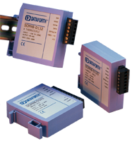
High quality 9B modules provide cost-effective protection and conditioning for a wide range of distributed data acquisition and control applications including process monitoring and control, remote data logging, product testing, and motion and motor speed control.

Our extensive line includes fixed and programmable sensor-to-computer and computer-to-analog output interface modules, RS-232/RS-485 converters, RS-485 repeaters, and applications software. Accessories include a complete selection of backpanels, DIN rail mounting options, interface cables, mounting racks, power supplies, and other accessory items.

All 9B products are CE Compliant and manufactured per RoHS Directive 2002/95/EC.

SCM9B-1000/2000/5000/D100
SENSOR-TO-COMPUTER MODULES

These isolated modules provide complete sensor/RS-232C or /RS-485 interfaces with 15-bit measurement resolution. They accept a variety of voltage, current, thermocouple, RTD/thermistor, strain gage, timer/frequency, and multichannel digital inputs/outputs

SCM9B-3000/4000
COMPUTER-TO-ANALOG OUTPUT MODULES

These are complete, isolated interfaces designed for remote installation and communication with host computers via standard RS-232C and RS-485 serial ports. They offer 12-bit resolution in a range of analog output voltages and currents.

SCM9B-A1000/2000/D192
CONVERTERS AND REPEATERS

These products convert RS-232C communication signal levels to the correct RS-485 signal requirements, and may also be configured as repeaters to extend communication bus lengths.
Certifications

Documents
Product Availability
Usually stock to 2-3 weeks

Dimensions & Accessories

Features

SCM9B Sensor-to-Computer Modules

  • 500Vrms Input Isolation
  • Programmable Scaling and Linearization
  • ASCII Command/Response Protocol
  • 15-bit Measurement Resolution
  • Continuous Self-Calibration
  • Analog Readback
  • DIN Rail Mountable D100 Series

SCM9B Computer-to-Analog Output Modules

  • 0-1V, ±1V, 0-5V, ±5V, 0-10V, ±10V, 0-20mA, 4-20mA Output Ranges
  • 500Vrms Output Isolation
  • 12-bit Output Resolution
  • Programmable 0.01V/s (mA/s) to 10,000V/s (mA/s) Output Slopes
  • Analog Readback
  • Data Scaling

SCM9B Converters and Repeaters

  • Transparent to Host
  • Optically Isolated Bidirectional Data Flows
  • Automatic Internal RS-485 Bus Supervision
  • DIN Rail Mountable D192 Model

SCM9B Configuration and Utility Software

PartNumber Description Purchase License Download User Manual Version Download Size
SCM9B-S300 SCM9B-S300 Utility Software
More Information
Free
2000 2.9 MB
SCM9B-S300
SCM9B-S300 Utility Software
More Information
Free
Version: 2000
Size: 2.9 MB

FAQ

Due to resource constraints on my computer, I'm unable to open the three dimensional CAD models provided on your website. Does Dataforth provide two demensional CAD models for download as well?
Two dimensional CAD models can be generated upon customer request. Please contact Customer Service for assistance.
What is the difference between the SCM9B-1000 series and the SCM9B-2000 series?
The SCM9B-1000 and the SCM9B-2000 have the same physical dimensions. The SCM9B-1000 hardware is similar to the SCM9B-2000 series in every respect except that the SCM9B-2000 contains built-in commands to create custom input-to-output transfer functions.
How does the load resistance of a module affect the noise at the output?
Noise at the output of a module is independent of load resistance.
How do I convert an RMS voltage to its corresponding peak voltage?
To convert an RMS voltage to its corresponding peak voltage, you simply take the RMS voltage value and multiply it by the square root of 2, or roughly 1.414. For example, 1500Vrms corresponds to a peak voltage of 1500 * 1.414 = 2121 Vp
If the input range of my signal conditioner is -1V to +1V and the output range is 0 to 10V, does this mean that it ignores polarity?
A signal conditioner with these I/O ranges does not mean that the module ignores the polarity of your voltage input. The output of voltage input modules are scaled linearly, meaning an input of -1V would correspond to an output of 0V, an input of 0V would correspond to an output of 5V, an input of +1V would correspond to an output of 10V, and so on.
Analog Devices announced a last time buy and discontinuance of their signal conditioning modules. Can I replace them with Dataforth signal conditioning modules?
Yes, in general, Dataforth signal conditioning modules are a direct replacement for all Analog Devices signal conditioning modules. e.g. "SCM5B35-xx: Linearized 4-Wire RTD Input Modules" will replace Analog Devices "5B35: Isolated 4 Wire RTD Input Signal Conditioning Module". Please note that Dataforth signal conditioning modules are RoHS II compliant.
Can Dataforth provide calibration reports for modules I purchased?
Yes we can provide calibration reports for the modules that you purchased. You can either a) visit https://www.dataforth.com/TestDataReport.aspx to search for Test Report Datasheets by Serial Number or b) you can send us a list of model numbers and their serial numbers to support@dataforth.com
Does Dataforth have any modules with continuous data streaming?
Yes, in the SCM9B series a number of modules can be ordered as continuously data streaming modules. To find out which SCM9B modules can be ordered with the data streaming option, by phone call technical support at 800 444 7644 press 2 or by email at support@dataforth.com. To order a data streaming SCM9B module add a “C” suffix to the model number, example: SCM9B-1251C accepts 4-20mA and provides streaming data on RS-232.

KEYWORDS/PHRASES: streaming, data streaming, continuous data streaming, SCM9B continuous data streaming
Is there a drawing which can help me locate the SCM9B mounting holes?
There is a mechanical drawing of the SCM9B modules at the end of the 9B data sheets on www.dataforth.com. A .pdf of the drawing is also in the Media Attachments box to the right of the topic main body.
What are the dimensions of the SCM9B series of modules?
The module dimensions of the SCM9B Series can be found on a drawing in www.dataforth,com. In the upper left of the home page under Explore our product offerings, point and click on Signal Conditioning, point and click on 9B Analog to Serial Isolated Modules. In the center column of the next page under SCM9B Series Product Family, click on the Adobe Acrobat symbol to the right of Dimensions. This displays a .pdf drawing of SCM9B module dimensions. The drawing maybe downloaded and saved.

A .pdf of the drawing is also in the Media Attachments box to the right of this topic's main body.

Keywords/Phrases: SCM9B, SCM9B mounting holes, SCM9B mechanical drawing, SCM9B dimensions drawing 9B dimensions drawing
How to select USB to RS-232 adapters for DTF products?
Contemporary computers do not have RS-232 ports, but USB ports instead. However, there are many USB to RS-232 adapters available. If the adapter is to be used with a device which uses the Modbus protocol or will be installed in a system which uses the Modbus protocol, the adapter must either be specified for use with Modbus or must be tested on a Modbus device for proper communications functioning. Selection criteria for Data Acquisition products: MAQ20-COM2, SLX300-10 These devices have USB ports. If an additional communications channel is needed, a USB RS-232 adapter can be used. The adapter in this case does not need handshake signals included. These devices both use the Modbus protocol. Selection criteria for Data Communications products: DCP485, LDM70, LDM85, LDM422, LDM485 These devices are externally powered and use transmit data, receive data, and ground for communications, and use various handshake signals to control particular functions. Refer to the specific user manual in the Media Attachments area to the right of this Content main body for usage instructions. DCP35, LDM35, LDM80 These devices are powered from the handshake and the transmit and receive data signals. The adapter in this case should have the handshake signals included. If the adapter does not have handshake signals included, use it for the transmit and receive data signals and power the device handshake inputs from separate positive and negative power supplies. Since the adapter could be installed between two computers and either one could initiate a data transfer, the adapter should be able to allow not only the USB side but also the RS-232 side to initiate the data transfer. LDM30 This device is externally powered and uses only transmit data, receive data, and ground for communications. RTS is connected to CTS internally. DTR, DSR, and RLSD (DCD) are connected to each other internally. The adapter in this case does not need handshake signals included. If there is a system requirement for handshake signals, then choose an adapter with handshake signals included. Selection criteria for Signal Conditioning products: SCM9B-A1000/A2000 These devices are externally powered and use only transmit data, receive data, and ground for communications. Handshake signals CTS, DSR, and RLSD (DCD or CD) are internally biased to their asserted state or high state, a positive voltage. The adapter in this case does not need handshake signals included. If there is a system requirement for handshake signals, then choose an adapter with handshake signals included.
Do the SCM9B-A1000 & SCM9B-A2000 have DIN rail mounting?
Neither the SCM9B-A1000 nor the SCM9B-A2000 has DIN rail mounting.
The SCM9B-D192, a DIN rail mountable module, is the closest equivalent of the SCM9B-A2000.

Keywords/Phrases: SCM9B DIN rail mounting, SCM9B DIN rail module
How do I verify module accuracy?
Long story short, they believe the modules may be less accurate than specified. The biggest error seems to be a low voltage (1-2V), with error decreasing as Vin approaches 10V. The biggest error at low voltage with error decreasing as Vin approaches 10V means that they are calculating error as % of reading. Accuracy of Dataforth modules is specified and calculated as % of Span. The method is the following. Set the test voltage. Apply it to the module input. Measure the voltage at the module input. Calculate the expected module output voltage using the measured input voltage. Measure the output voltage. Calculate the % of Span error by the following formula. Accuracy error % Span = ((Measured Vout – Calculated Vout) / Output Span V ) x 100 This method works for input or output modules. Keywords/Phrases: Module accuracy, accuracy %, accuracy % of Span, Dataforth method for calculating Span accuracy

Was this content helpful?
Thank you for your feedback!
Menu
Top